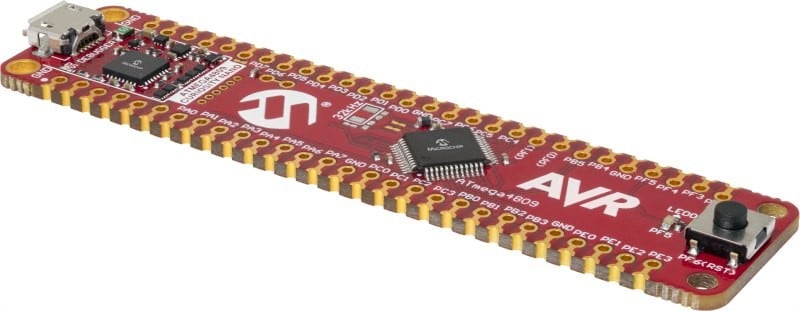
The ATtiny1607 Curiosity Nano Evaluation Kit is the ideal platform for rapid prototyping with tinyAVR MCUs. The USB-powered kit features an on-board programmer/debugger that seamlessly integrates with MPLAB® X and Microchip Studio Integrated Development Environments (IDEs). The small form factor makes the board ideal for breadboard soldering, or you can combine it with the Curiosity Nano Base for Click boardsTM, which features multiple mikroBUS™ sockets so you can easily add sensors, actuators or communications interfaces from Mikroelektronika’s extensive selection of Click boards.
Significantly reduce your development time with Atmel START, our intuitive, web-based graphical configuration tool for embedded projects. While you navigate through the easy-to-use interface, Atmel START generates factory-validated C-code to help get your design started quickly. Get started today at start.atmel.com.
With a few clicks, Atmel START projects can be imported into the Microchip Studio Integrated Development Environment (IDE) and can be easily modified at any time.
Event System
The Event System allows peripherals to
communicate directly with each other without involving the Central
Processing Unit (CPU) or bus resources. The Event System network is
independent of the traditional data bus paths. This means that different
triggers at the peripheral level can result in an event, such as a
timer’s interrupts triggering an action in another peripheral. The Event
System has three independent channels for direct
peripheral-to-peripheral signaling. This is a deterministic signaling
method and a perfect fit for real-time applications. The events are
handled at the peripheral level regardless of if the CPU is occupied
handling interrupts or in sleep mode.
On-Board Safety and Monitoring
Add robustness and reliability to an application by utilizing built-in features such as the Windowed Watchdog Timer (WDT), the Cyclic Redundancy Check (CRC) feature to scan the Flash memory and fault detection using the Event System, to support safety critical applications. Take advantage of full supply voltage monitoring capabilities with safety features like a Voltage Level Monitor (VLM), a Brown-Out Detector (BOD) and Power-On Reset (POR). All of these features are integrated into each of the ATtiny1607 family members, enabling the design of safer and more robust applications.
Cyclic Redundancy Check (CRC)
The Cyclic Redundancy Check (CRC) is used to verify that there is no corruption in the application code. The CRC scan calculates the checksum of the entire Flash memory, or parts of it, and automatically compares it with the expected result. This enables it to detect errors in program memory fast and efficiently. The CRC can scan at run time, or it can run during reset to ensure that the Flash is valid before the CPU is allowed to execute the code. When the CRC scan is done at run time it temporarily halts the CPU to complete the scan quickly.
Windowed Watchdog Timer (WWDT)
The Windowed Watchdog Timer
(WWDT) is a system supervisory circuit that generates a reset if
software anomalies, like runaway or deadlocked code, are detected within
a configurable critical window. When enabled, the WWDT is a constantly
running timer configured to a predefined timeout period. If the WWDT is
not reset within the timeout period, it will issue a system reset.
Power-On Reset (POR)
Safe startup of every device is key.
During power-up of a device, it is important to give the entire device a
reset to put everything in a known state. It is equally important that
memories and digital logic have a sufficient supply voltage to operate
correctly. When the voltage rises, the POR is activated and will hold
the device in reset until the voltage is above a fixed threshold value.
The POR will remain enabled as long as the device is powered.
Brown-Out Detect (BOD)
The
Brown-Out Detect (BOD) feature monitors the power supply and compares
the voltage against a programmable threshold. The BOD is used to ensure
erroneous code execution and memory writes do not occur by verifying
that the device is operating within specification, which guarantees that
the supply voltage is sufficient to run at the selected CPU speed. If
the voltage falls below the set threshold, the BOD issues a system reset
and will hold the device in reset until the voltage has risen above the
set threshold again.
Voltage Level Monitoring (VLM)
The
Voltage Level Monitor (VLM) monitors the power supply and can be
configured to generate an interrupt request when the voltage passes
below a given threshold. This can act as an early warning to the
application that the supply voltage is passing the VLM threshold, and
the application can take the necessary actions to safely prepare for a
possible brown-out situation (power loss). A safe shutdown can benefit
from the fast EERPOM page-write and store critical system parameters.
The threshold is configured by the user and is expressed in percentage
above the configured BOD level.
Product | Status | 5K Pricing | CPU | Architecture | Family | Program Memory Size (KB) | Program Memory Size (KWords) | Bootload capable | SRAM (Bytes) | Emulated EEPROM in Flash | Max I/O Pins | Pin count | Max CPU Speed (MHz) | Peripheral Pin Select / Pin Muxing | Vbat/Vddbu battery backup | Brown-Out Reset | Low Voltage Detection | Power On Reset | Internal Oscillator | Hardware RTCC/RTC | Watch Dog Timer | Number of Comparators | Number of Op Amps | Number of ADCs | ADC Input | Max ADC Resolution (Bits) | Max ADC Sampling Rate (ksps) | ADC with Computation | Number of DACs | DAC Outputs | Max DAC Resolution (Bits) | Internal Voltage Reference (Bandgap) | Zero Cross detect | Slope Compensation / Programmable Ramp Generator | Data Signal Modulator | CTMU | Max 8-Bit Digital Timers | Max 16-Bit Digital Timers | Signal Measurement Timer | Hardware Limit Timer | Stand alone PWMs | Capture / Compare/PWM (CCP) | Enhanced Capture/Compare/PWM (ECCP) | Max PWM outputs (including complementary) | Number of PWM Time Bases | PWM Max Resolution (Bits) | Quadrature Encoder Interface | Angular Timer | Math Accelerator | UART | SPI | I2C | Number of USB Modules | USB Interface | USB Active Clock Tuning | Number of CAN Modules | CAN Transmit Buffers | CAN Receive Buffers | Ethernet | LIN | IrDA | Parallel Port | Class B Support | CRC | Configurable Logic Cell (CLC/CCL) | Complementary Waveform Generator / Complementary Output Generator | Numerically Controlled Oscillator | Programmable Switched Mode Controller | Hardware Cap Voltage Divider | Cap. Touch Channels | Segmented LCD | Keeloq Hardware | Crypto Engine | JTAG | Temp Range Min | Temp Range Max | Operation Voltage Min (V) | Operation Voltage Max (V) | High Voltage Capable | Packages |
---|---|---|---|---|---|---|---|---|---|---|---|---|---|---|---|---|---|---|---|---|---|---|---|---|---|---|---|---|---|---|---|---|---|---|---|---|---|---|---|---|---|---|---|---|---|---|---|---|---|---|---|---|---|---|---|---|---|---|---|---|---|---|---|---|---|---|---|---|---|---|---|---|---|---|---|---|---|---|---|---|
ATTINY402 | In Production | $0.29 | 8-bit AVR MCU | 8 | 8-bit MCU | 4 | 2 | Yes | 256 | 128 / HEF | 6 | 8 | 20 | Yes | No | Programmable BOR | None | Yes | 20 MHz, 32 kHz | N/A | Yes | 1 | 0 | 0 | 12 | 10 | 0 | No | 0 | 0 | 0 | Yes | No | 0 | 0 | No | 0 | 2 | 0 | 0 | 6 | 0 | 0 | 0 | 0 | 8 | 0 | No | No | 1 | 1 | 1 | 0 | None | No | 0 | 0 | 0 | None | No | No | No | No | Yes | 1 | 0 | 0 | 0 | No | 9 | 0 | No | No | None | -40 | 125 | 1.8 | 5.5 | No | 8/SOIC |
ATTINY404 | In Production | $0.36 | 8-bit AVR MCU | 8 | 8-bit MCU | 4 | 2 | Yes | 256 | 128 / HEF | 12 | 14 | 20 | Yes | No | Programmable BOR | None | Yes | 20 MHz, 32 kHz | N/A | Yes | 1 | 0 | 0 | 12 | 10 | 0 | No | 0 | 0 | 0 | Yes | No | 0 | 0 | No | 0 | 2 | 0 | 0 | 4 | 0 | 0 | 0 | 0 | 8 | 0 | No | No | 1 | 1 | 1 | 0 | None | No | 0 | 0 | 0 | None | No | No | No | No | Yes | 1 | 0 | 0 | 0 | No | 9 | 0 | No | No | None | -40 | 125 | 1.8 | 5.5 | No | 14/SOIC |
ATTINY406 | In Production | $0.43 | 8-bit AVR MCU | 8 | 8-bit MCU | 4 | 2 | Yes | 256 | 128 / HEF | 18 | 20 | 20 | Yes | No | Programmable BOR | None | Yes | 20 MHz, 32 kHz | N/A | Yes | 1 | 0 | 0 | 12 | 10 | 0 | No | 0 | 0 | 0 | Yes | No | 0 | 0 | No | 0 | 2 | 0 | 0 | 6 | 0 | 0 | 0 | 0 | 8 | 0 | No | No | 1 | 1 | 1 | 0 | None | No | 0 | 0 | 0 | None | No | No | No | No | Yes | 1 | 0 | 0 | 0 | No | 9 | 0 | No | No | None | -40 | 125 | 1.8 | 5.5 | No | 20/SOIC, 20/VQFN |
ATTINY804 | In Production | $0.43 | 8-bit AVR MCU | 8 | 8-bit MCU | 8 | 4 | Yes | 512 | 128 / HEF | 12 | 14 | 20 | Yes | No | Programmable BOR | None | Yes | 20 MHz, 32 kHz | N/A | Yes | 1 | 0 | 0 | 12 | 10 | 0 | No | 0 | 0 | 0 | Yes | No | 0 | 0 | No | 0 | 2 | 0 | 0 | 6 | 0 | 0 | 0 | 0 | 8 | 0 | No | No | 1 | 1 | 1 | 0 | None | No | 0 | 0 | 0 | None | No | No | No | No | Yes | 1 | 0 | 0 | 0 | No | 0 | No | No | None | -40 | 125 | 1.8 | 5.5 | No | 14/SOIC | |
ATTINY806 | In Production | $0.48 | 8-bit AVR MCU | 8 | 8-bit MCU | 8 | 4 | Yes | 512 | 128 / HEF | 18 | 20 | 20 | Yes | No | Programmable BOR | None | Yes | 20 MHz, 32 kHz | N/A | Yes | 1 | 0 | 0 | 12 | 10 | 0 | No | 0 | 0 | 0 | Yes | No | 0 | 0 | No | 0 | 2 | 0 | 0 | 6 | 0 | 0 | 0 | 0 | 8 | 0 | No | No | 1 | 1 | 1 | 0 | None | No | 0 | 0 | 0 | None | No | No | No | No | Yes | 1 | 0 | 0 | 0 | No | 0 | No | No | None | -40 | 125 | 1.8 | 5.5 | No | 20/SOIC, 20/VQFN | |
ATTINY807 | In Production | $0.59 | 8-bit AVR MCU | 8 | 8-bit MCU | 8 | 4 | Yes | 512 | 128 / HEF | 22 | 24 | 20 | Yes | No | Programmable BOR | None | Yes | 20 MHz, 32 kHz | N/A | Yes | 1 | 0 | 1 | 12 | 10 | 0 | Yes | 0 | 0 | 0 | Yes | No | 0 | 0 | No | 0 | 2 | 0 | 0 | 6 | 0 | 0 | 0 | 0 | 8 | 0 | No | No | 1 | 1 | 1 | 0 | None | No | 0 | 0 | 0 | None | Yes | Yes | No | No | Yes | 1 | 0 | 0 | 0 | No | 0 | No | No | None | -40 | 125 | 1.8 | 5.5 | No | 24/VQFN | |
ATTINY1604 | In Production | $0.46 | 8-bit AVR MCU | 8 | 8-bit MCU | 16 | 8 | Yes | 1024 | 256 / HEF | 12 | 14 | 20 | Yes | No | Programmable BOR | None | Yes | 20 MHz, 32 kHz | N/A | Yes | 1 | 0 | 1 | 12 | 10 | 0 | Yes | 0 | 0 | 0 | Yes | No | 0 | 0 | No | 0 | 2 | 0 | 0 | 6 | 0 | 0 | 0 | 0 | 8 | 0 | No | No | 1 | 1 | 1 | 0 | None | No | 0 | 0 | 0 | None | Yes | Yes | No | No | Yes | 1 | 0 | 0 | 0 | No | 0 | No | No | None | -40 | 125 | 1.8 | 5.5 | No | 14/SOIC | |
ATTINY1606 | In Production | $0.49 | 8-bit AVR MCU | 8 | 8-bit MCU | 16 | 8 | Yes | 1024 | 256 / HEF | 18 | 20 | 20 | Yes | No | Programmable BOR | None | Yes | 20 MHz, 32 kHz | N/A | Yes | 1 | 0 | 1 | 12 | 10 | 0 | Yes | 0 | 0 | 0 | Yes | No | 0 | 0 | No | 0 | 2 | 0 | 0 | 6 | 0 | 0 | 0 | 0 | 8 | 0 | No | No | 1 | 1 | 1 | 0 | None | No | 0 | 0 | 0 | None | Yes | Yes | No | No | Yes | 1 | 0 | 0 | 0 | No | 0 | No | No | None | -40 | 125 | 1.8 | 5.5 | No | 20/SOIC, 20/VQFN | |
ATTINY1607 | In Production | $0.62 | 8-bit AVR MCU | 8 | 8-bit MCU | 16 | 8 | Yes | 1024 | 256 / HEF | 22 | 24 | 20 | Yes | No | Programmable BOR | None | Yes | 20 MHz, 32 kHz | N/A | Yes | 1 | 0 | 1 | 12 | 10 | 0 | Yes | 0 | 0 | 0 | Yes | No | 0 | 0 | No | 0 | 2 | 0 | 0 | 6 | 0 | 0 | 0 | 0 | 8 | 0 | No | No | 1 | 1 | 1 | 0 | None | No | 0 | 0 | 0 | None | Yes | Yes | No | No | Yes | 1 | 0 | 0 | 0 | No | 0 | No | No | None | -40 | 125 | 1.8 | 5.5 | No | 24/VQFN | |
ATTINY202 | In Production | $0.29 | 8-bit AVR MCU | 8 | 8-bit MCU | 2 | 1 | Yes | 128 | 64 / HEF | 6 | 8 | 20 | Yes | No | Programmable BOR | None | Yes | 20 MHz, 32 kHz | N/A | Yes | 1 | 0 | 0 | 12 | 10 | 0 | No | 0 | 0 | 0 | Yes | No | 0 | 0 | No | 0 | 2 | 0 | 0 | 4 | 0 | 0 | 0 | 0 | 8 | 0 | No | No | 1 | 1 | 1 | 0 | None | No | 0 | 0 | 0 | None | No | No | No | No | Yes | 1 | 0 | 0 | 0 | No | 9 | 0 | No | No | None | -40 | 125 | 1.8 | 5.5 | No | 8/SOIC |
ATTINY204 | In Production | $0.36 | 8-bit AVR MCU | 8 | 8-bit MCU | 2 | 1 | Yes | 128 | 64 / HEF | 12 | 14 | 20 | Yes | No | Programmable BOR | None | Yes | 20 MHz, 32 kHz | N/A | Yes | 1 | 0 | 0 | 12 | 10 | 0 | No | 0 | 0 | 0 | Yes | No | 0 | 0 | No | 0 | 2 | 0 | 0 | 4 | 0 | 0 | 0 | 0 | 8 | 0 | No | No | 1 | 1 | 1 | 0 | None | No | 0 | 0 | 0 | None | No | No | No | No | Yes | 1 | 0 | 0 | 0 | No | 9 | 0 | No | No | None | -40 | 125 | 1.8 | 5.5 | No | 14/SOIC |
This video provides an overview of the ATtiny1607 family of AVR® microcontrollers. This family is equipped with high-speed integrated analog, hardware-based Core Independent Peripherals (CIPs) and low-power performance for efficient, real-time control applications in a small physical footprint to help optimize board layout.