How to Simplify Motor Position Control Systems in Aviation Applications
We provide a practical demonstration of a linear actuator control system for aircraft and defense applications. The demonstration simplifies traditional solutions by using a highly integrated motor acquisition SOC and dual microcontrollers (MCUs).

Linear Actuator Control System for Aircraft and Defense Applications
As aircraft weight, size and speed have increased, more efficient and highly reliable semiconductor solutions are required for flight control surface actuation.
In this blog post, we will demonstrate a linear actuator control system using an LX4580 24-channel data acquisition system with synchronized motor control interface System-on-Chip (SoC) with dual ATSAMV71 MCUs.
The aviation industry is shifting to a More Electric Aircraft (MEA) that replaces mechanical, hydraulic and pneumatic systems with an electric solution. This results in a significant reduction in weight that in turn reduces fuel consumption and emissions. An added benefit to using less mechanical content is an increase in reliability and a reduction in maintenance and ownership expenses.
The LX4580 Actuation SoC
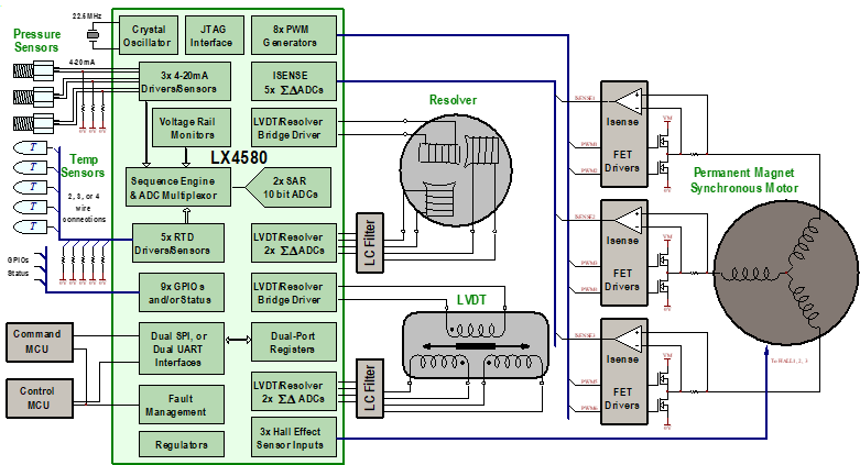
The LX4580 is an analog front-end for motor-actuator control systems working under stringent standards such as DO-160. The LX4580 interfaces with MCUs or Field-Programmable Gate Arrays (FPGAs) to execute digital control system algorithms in real time. Dual high-speed Serial Peripheral Interfaces (SPIs) or Universal Asynchronous Receiver and Transmitter (UART) interfaces offer simultaneous dual-port register access for redundant command/monitor (COM/MON) system architectures. The interfaces use ECC encoding to provide 1-bit error correction and 2-bit error detection in every 16-bit data transaction. Sequential logic is implemented with Triple Mode Redundancy (TMR) to protect against Single-Event Upsets (SEUs). Analog inputs, LVDT drivers and logic I/Os can be cold spared, allowing two LX4580s to operate in a redundant configuration with one powered on while the other is off or in reset. System configuration, calibration and interface setup data is stored in internal One-Time Programmable (OTP) memory and automatically loaded at power-up. Figure 1 illustrates the functions internal to the LX4580 and external connections in a typical application.

Figure 1: Typical Actuation Application
Typical Control System Architecture
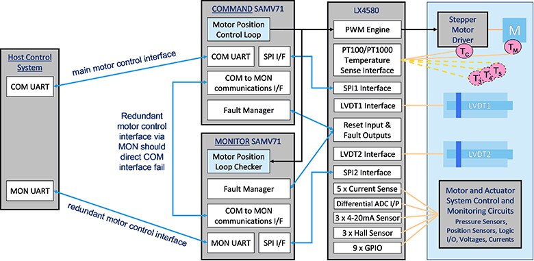
Motor position and linear actuation control systems used in aircraft and airborne defense systems can be implemented using an LX4580 motor acquisition SoC with dual ATSAMV71Q21 MCUs. The MCUs run the motor control loop and generate motor control signals in a classic command/monitor (COM/MON) dual-controller redundant control system (Figure 2). The LX4580 SoC manages the sensors—in this case, an LVDT and two temperature sensors—and drives the LVDT primary directly, calculates the RMS of the two LVDT secondaries and automates temperature sensing based on PT100 or TP1000 remote sensors.

Figure 2: COM/MON Motor Control System With Dual Processors
In order to provide a practical demonstration of this control system implementation, we've developed source code for a motor position control system using an LVDT as a position feedback sensor as the core of a larger control system. The motor drive hardware is simplified by using an off-the-shelf stepper motor controller instead of using the LX4580’s Pulse-Width Modulation (PWM) outputs and current sense inputs.
COM Processor Functions
The COM processor is the main motor control processor. Its functions are:
- Communicate to the main system controller for position target setting and high level diagnostics
- Acquire system position, temperatures and other status using LX4580
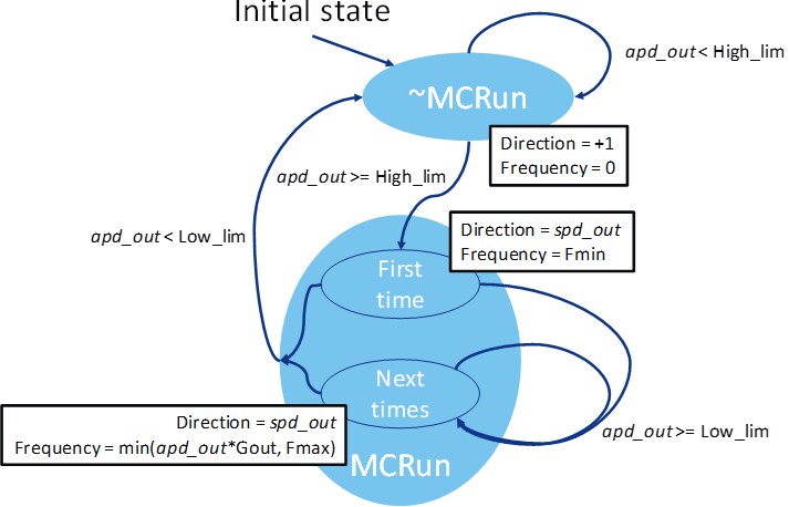
- Control the TB6600 motor driver based on a Phase Detect (PD) loop with hysteresis (Figure 3 below)
- Perform error checking
- Communicate results to the MON processor to compare results and read MON error status

Figure 3: Phase Detect Loop
MON Processor Functions
The MON processor is the backup motor control processor. Its functions are:
- Communicate to the main system controller for position target setting, high level diagnostics and error reporting
- Acquire position (independently using the LX4580's 2nd LVDT channel), temperatures and other status using LX4580
- Monitor the COM processor control outputs
- Measure the frequency of the PULSE waveform commanding motor steps
- Sense polarity of the DIR waveform commanding motor direction
- Run the same control motor driver algorithm as the COM processor but based on MON processor gathered data
- Communicate to the COM processor to get COM results and report errors
- Error checking for data inconsistencies (PULSE frequency, position, temperatures) between COM and MON
Communications between the COM and MON processors use a UART interface to access shared memory regions.
PC (Main System Controller)
The PC software runs a command system in Python, which communicates to both COM and MON processors over individual USB interfaces. Commands are dispatched to both COM and MON processors to allow the MON processor to detect a COM or MON interface failure. On error detection, the MON processor isolates COM commands from the motor and will wait until higher level control can service the error and potentially restart the control process.
For a complete description of the demonstration system and more information on the LX4580 including a full data sheet, visit the LX4580 product page. For more information on ATSAMV71Q21 MCUs, visit the ATSAMV71Q21 product page.