
It is often necessary to run some type of computation or analysis on your Analog-to-Digital Converter (ADC) results, whether it is filtering or verifying if a value falls within a certain range or not. Software is normally needed to handle these computations which ties up your Central Processing Unit (CPU). Using an Analog-to-Digital Converter with Computation and Context Saving provides the ability to do complex operations on the data collected by the ADC, as well as ADC channel sequencing and configuration management with zero CPU intervention.
These on-chip features eliminate the need for you to write code to see if your readings fall inside or outside of a certain window. You also will not need to average sample readings, filter sample readings or even manage contextual channel configurations for your application. The intelligent analog ADC peripheral functions independently instead of tying up CPU resources.
Click the button below to access a live and interactive demo of the ADC rejecting noise present on the signal. The type of noise injected, the amount of oversampling and other demo parameters can be set by taking control of the demo.
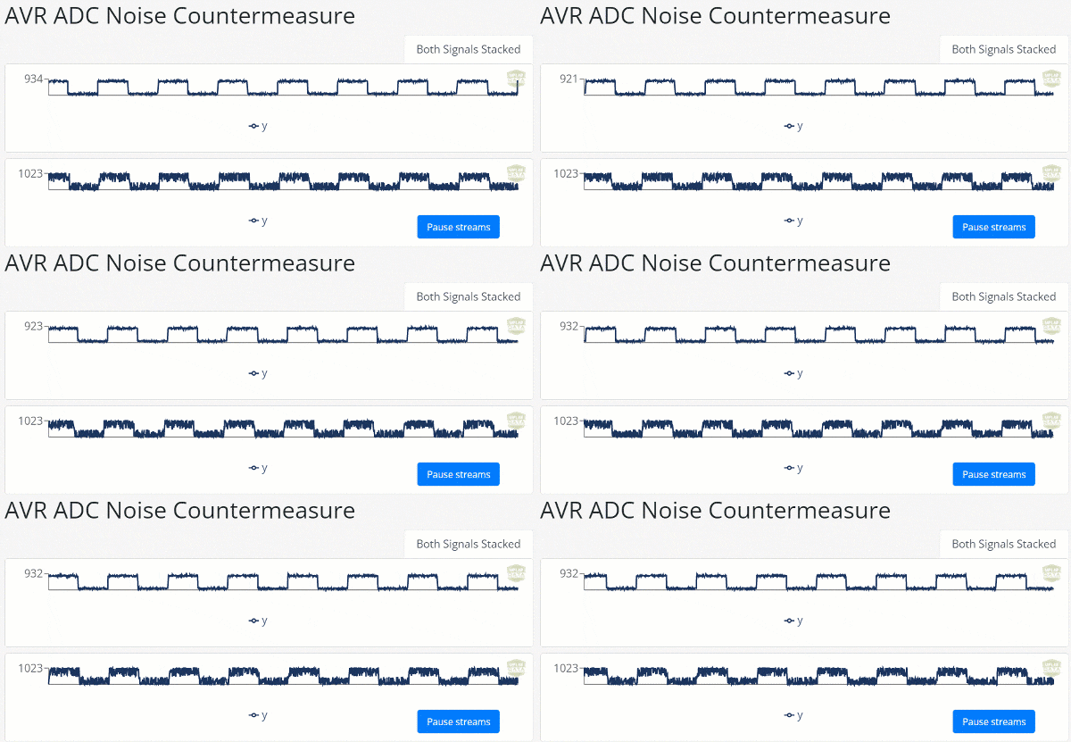
Low-Pass Filtering mode gathers data until a user-defined number of samples has been collected. A customizable digital low-pass filter within the ADC is then applied to the accumulated value. This enables you to reduce the amount of high-frequency noise on the average.
Threshold Comparison (for PIC MCUs) and Window Comparison (for AVR MCUs) are features that allow you to generate interrupts under certain conditions. An interrupt can be generated if an ADC read falls inside, outside, above or below a configured threshold or window. With this advanced capability, ADC values can be monitored and can alert your system when certain criteria is met without needing CPU intervention.
Some PIC MCU ADCs offer a Capacitive Voltage Divider, which is extremely useful in capacitive touch applications. It executes the capacitance measurement sequence within the module, so the ADC output can be directly used as the touch sensing data. This feature greatly reduces the code size and execution time compared to using a basic software library.
Most on-chip ADCs on PIC and AVR MCUs can be triggered by an external or internal signal. This feature allows you to precisely control the sampling period of your ADC without any CPU intervention.
The ADCs equipped with a PGA can apply a selective gain (2x, 4x, … 16x) to the input voltage prior to the ADC sampling, which enables the measurement of small amplitude signals.
Some MCUs feature one or more integrated op amps which can also be internally connected to the ADC to create a more flexible gain stage.
Some ADCs in PIC® and AVR® MCUs can utilize differential inputs to improve common-mode noise immunity and resolution in a narrower range. The conversion gives a signed result of the positive ADC input channel minus the negative ADC input channel.
Context saving and channel sequencing on PIC MCUs automate the management of multiple input channels to the ADC by eliminating the need to reconfigure the ADC registers every time a new channel is selected. This reduces software overhead and simplifies firmware design when developing sensor interfaces.
Channel grouping allows you to connect multiple input channels together into a single input on the ADC. This enables the ADC to detect a change in input on any of the grouped inputs with a single measurement.
Free Running mode (for AVR MCUs) and Continuous Operation mode (for PIC MCUs) are available for most ADCs on recent PIC and AVR devices. In this mode, the ADC only needs to be triggered once. After being initialized, the ADC will continue to trigger itself until stopped. This enables the ADC to continuously monitor your system without needing CPU intervention.
The enhanced ADCs can accumulate and/or average samples independently of the CPU core for improved measurements with no CPU overhead. The averaging modes can improve the Signal-to-Noise Ratio (SNR) in analog signals.
Low-Pass Filtering mode gathers data until a user-defined number of samples has been collected. A customizable digital low-pass filter within the ADC is then applied to the accumulated value. This enables you to reduce the amount of high-frequency noise on the average.
Threshold Comparison (for PIC MCUs) and Window Comparison (for AVR MCUs) are features that allow you to generate interrupts under certain conditions. An interrupt can be generated if an ADC read falls inside, outside, above or below a configured threshold or window. With this advanced capability, ADC values can be monitored and can alert your system when certain criteria is met without needing CPU intervention.
Some PIC MCU ADCs offer a Capacitive Voltage Divider, which is extremely useful in capacitive touch applications. It executes the capacitance measurement sequence within the module, so the ADC output can be directly used as the touch sensing data. This feature greatly reduces the code size and execution time compared to using a basic software library.
Most on-chip ADCs on PIC and AVR MCUs can be triggered by an external or internal signal. This feature allows you to precisely control the sampling period of your ADC without any CPU intervention.
The ADCs equipped with a PGA can apply a selective gain (2x, 4x, … 16x) to the input voltage prior to the ADC sampling, which enables the measurement of small amplitude signals.
Some MCUs feature one or more integrated op amps which can also be internally connected to the ADC to create a more flexible gain stage.
Some ADCs in PIC® and AVR® MCUs can utilize differential inputs to improve common-mode noise immunity and resolution in a narrower range. The conversion gives a signed result of the positive ADC input channel minus the negative ADC input channel.
Context saving and channel sequencing on PIC MCUs automate the management of multiple input channels to the ADC by eliminating the need to reconfigure the ADC registers every time a new channel is selected. This reduces software overhead and simplifies firmware design when developing sensor interfaces.
Channel grouping allows you to connect multiple input channels together into a single input on the ADC. This enables the ADC to detect a change in input on any of the grouped inputs with a single measurement.
Free Running mode (for AVR MCUs) and Continuous Operation mode (for PIC MCUs) are available for most ADCs on recent PIC and AVR devices. In this mode, the ADC only needs to be triggered once. After being initialized, the ADC will continue to trigger itself until stopped. This enables the ADC to continuously monitor your system without needing CPU intervention.
The enhanced ADCs can accumulate and/or average samples independently of the CPU core for improved measurements with no CPU overhead. The averaging modes can improve the Signal-to-Noise Ratio (SNR) in analog signals.
Low-Pass Filtering mode gathers data until a user-defined number of samples has been collected. A customizable digital low-pass filter within the ADC is then applied to the accumulated value. This enables you to reduce the amount of high-frequency noise on the average.
Threshold Comparison (for PIC MCUs) and Window Comparison (for AVR MCUs) are features that allow you to generate interrupts under certain conditions. An interrupt can be generated if an ADC read falls inside, outside, above or below a configured threshold or window. With this advanced capability, ADC values can be monitored and can alert your system when certain criteria is met without needing CPU intervention.
Some PIC MCU ADCs offer a Capacitive Voltage Divider, which is extremely useful in capacitive touch applications. It executes the capacitance measurement sequence within the module, so the ADC output can be directly used as the touch sensing data. This feature greatly reduces the code size and execution time compared to using a basic software library.
Most on-chip ADCs on PIC and AVR MCUs can be triggered by an external or internal signal. This feature allows you to precisely control the sampling period of your ADC without any CPU intervention.
Implemented features vary by device family. Please consult the device's data sheet for specifics.
Please visit the full parametric chart. If you still cannot find the chart you are looking for, please complete our Website Feedback Form to notify us of this issue.
Have you ever wanted to filter noise on an incoming analog signal? Would you like your system to notify you when an analog signal goes above, below, inside or outside of a defined window? If so, then this video will explain how to use the Analog-to-Digital Converter with Computation or ADCC to average a noisy signal from an incoming sensor. This video will also show how to use the ADCC threshold comparison to give an interrupt any time the input signal falls outside of a certain window.
The video demonstrates how easy it is to add capacitive sensing into an application using core independent intelligent analog features and the MPLAB® Xpress Development Platform. Burst Averaging capabilities of the Analog-to-Digital Converter with Computation (ADCC) are used to read the voltage level based on the capacitance of a sensor made with conductive ink. The 10-bit ADCC value will be transmitted over the serial port to a computer running a terminal program. The ADCC value will register a higher value when the sensor is alone and a lower value when an object such as a finger touch is introduced.

Have you ever wondered how to use the window comparator on the ADC in Atmel START? Or have you ever wondered how you can use the accumulation on the ADC to filter analog readings? Have you ever wondered simply how to set up the ADC peripheral in START? Well this tutorial will answer these questions and more such as how to set up the advanced ADC, using the window comparator to generate interrupts, and filtering analog readings. By the end of this tutorial, you should have a better understanding of how the analog to digital converter is configured and you should also understand some of the advanced capabilities available on the analog to digital converter in Atmel START. Be sure to subscribe to our YouTube channel and follow our twitter page @MicrochipTech. Part used in this video is the ATMEGA4809.

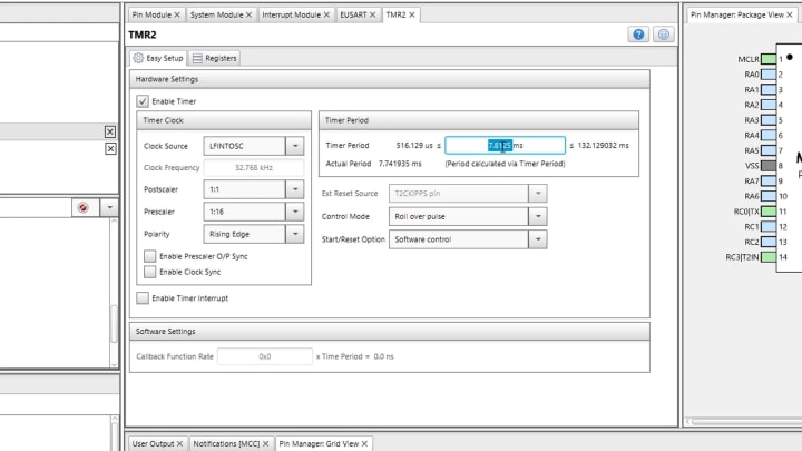
Do you need to filter a noisy incoming signal? Have you ever wondered how to set up the low pass filter on a PIC micro controller? This video tutorial will explain how to configure and use the low pass filter on the ADCC peripheral to modify a square wave as well as filter periodic noise from a DC signal.

|
Title
| |
|---|---|
| Analog-to-Digital Converter with Computation | Download |
| PIC16/PIC18 ADC2 Technical Brief | Download |
| Maximizing the Signal: Tips and Tricks to Properly Acquiring Analog Signals | Download |
| Getting Started with ADCC for PIC18 | Download |
| Analog Sensor Measurement and Acquisition | Download |
| How to Use Force Sensitive Resistor with 12-bit ADC | Download |
Live Chat
No problem. Chat with our engineering experts or schedule a call that's convenient for you.
Privacy Policy
These cookies are necessary for the Microchip website to function and cannot be switched off in our systems. They are usually only set in response to actions made by you which amount to a request for services, such as setting your privacy preferences, logging in or filling in forms. You can set your browser to block or alert you about these cookies, but some parts of the site will not work. These cookies do not store any personally identifiable information.
By accepting these cookies, you allow Microchip to offer you enhanced functionality and personalized experiences on our website. These cookies may be set by us or trusted third-party providers whose services we integrate. Without these cookies, some features and services may not work as intended.
These cookies may be set through our site by our advertising partners. They may be used by those companies to build a profile of your interests and show you relevant adverts on other sites. They do not store directly personal information but are based on uniquely identifying your browser and internet device. If you do not allow these cookies, you will experience less targeted advertising.
These cookies allow Microchip to count web page visits and traffic sources, so Microchip can measure and improve the performance of our experiences. These cookies help Microchip to know which experiences are the most and least popular and see how device owners interact with the experience. All information these technologies collect is aggregated. If the device owner does not allow these technologies, then Microchip will not know when the device owner visited or how the device owner interacted with our website
