Detect Overcurrent Conditions with AVR® DB Family of MCUs
Protect persons and property by using the internal OPAMPs on the AVR® DB family of MCUs to detect an overcurrent fault and shutdown the load.

One of the symptoms of a motor failure or obstruction is an increase in motor current. The increased current draw of the motor generates more heat, which can damage the motor or present a hazard to persons and property. To detect this, the internal operational amplifiers on the AVR® DB family of MCUs can be used to monitor the current through the motor and turn it off in the event of a current spike.
Walking Through the Schematic
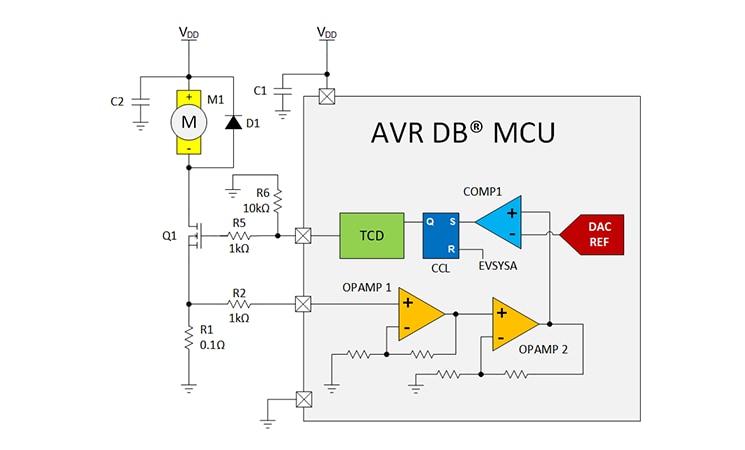
Application Note AN3860 creates a simple motor controller with overcurrent detection and automatic calibration. The demo schematic is shown in Figure 1. For motor control, the Timer-Counter D (TCD) is used to generate a PWM waveform which drives the gate of transistor Q1. The motor current flows through Q1 and R1 to ground, inducing a small voltage proportional to the current. Resistor R2 is implemented as a current limiting resistor – in the event of a high-voltage spike, this resistor significantly limits the input current into the microcontroller. Resistor R5 is used to limit the current into the gate of Q1 when switching the transistor, and resistor R6 is used as a pull-down to keep the transistor off while the microcontroller initializes. Finally, resistor R3 is used as a part of the gain network of OP1.
For testing, a small DC fan motor (M1) was used. Diode D1 is connected across the motor as a free-wheeling diode to suppress the high-voltage negative spike from the motor switching off. Capacitor C2 provides a source of low-impedance charge to help start the motor. Lastly, capacitor C1 is a decoupling capacitor for the MCU. This capacitor is pre-installed on the AVR DB Curiosity Nano Evaluation Kit (EV35L43A).
Not shown on the schematic is the pushbutton and indicator LED on the Curiosity Nano. The pushbutton is used to trigger a motor restart – in other applications, a more sophisticated auto-restart or other startup process can be implemented. The LED indicator on the Curiosity Nano is used to indicate the status of the calibration process.
Setting the OPAMPs
This application utilizes 2 of the internal operational amplifiers as a cascaded non-inverting amplifier. Cascading the OPAMPs together like this creates a higher gain and provides more gain flexibility in the design.
Initialization and Calibration of the Program
During initialization, the microcontroller runs the motor and determines the appropriate overcurrent limit by incrementing the analog comparator’s digital-to-analog converter reference (DACREF) by 50mV steps until the motor does not trigger the Analog Comparator (AC) threshold within a 100ms window.
After finding the correct level, the AC is connected to the S input of an S-R flip-flop (see Figure 1). If the comparator trips, then the flip-flop will be set and will shut down the TCD. The R-input of this flip-flop is connected to Software Event A (SWEVENTA), which is used to restart the motor.
Operation of the Example
On power-up, the microcontroller starts up the motor and begins calibration. When calibration is complete, the overcurrent protection is armed for the motor. If the motor exceeds the current limit, then the TCD will stop outputting a PWM signal. Pressing the pushbutton on the Curiosity Nano will trigger a restart and recalibration (of the motor current).
Simulating this Circuit
MPLAB® Mindi™ Analog Simulator, available for free, was used to simulate this application. By simulating the application, developers and engineers can save time by reducing the number of prototype iterations required to implement a design. The OPAMP models for the AVR DB are created from collected data on this OPAMP and are included in the 8.4 release of Mindi.
Conclusion
The internal operational amplifiers in the AVR DB family create new use cases for 8-bit microcontrollers. In this example, 2 of these internal OPAMPs are used to detect an overcurrent condition in a fan motor. This could be used to enhance the long-term reliability of products.
Read more about this application note (AN3860) here: AN3860
Visit the AVR® DB Homepage: AVR® DB Product Family MCUs