MEMS Mirror Steering
Static and Dynamic Laser Beam Steering
What is MEMS?
Microelectromechanical Systems (MEMS) is a technology that allows the fabrication of miniature mechanical and electro-mechanical devices using silicon fabrication techniques. Since they are fabricated with the same techniques used to create semiconductor ICs, it is possible to manufacture different MEMS structures reliably and cost effectively. MEMS systems are found in a variety of fields including sensors, RF timing, microfluidics and mirrors for optical signal processing.
What is MEMS Mirror Steering?
Given the proliferation of lasers in many applications, mirrors are a growing market for MEMS technology. MEMS mirror steering uses a MEMS-based mirror to deflect a laser beam in both static and dynamic operations. Static operation requires the mirror to deflect to a known angle accurately and maintain the angle almost indefinitely without significant drift. Dynamic operation requires the mirror to be able to track a programmed path accurately with fast response and high resolution.
What Are the Trends in MEMS Mirror Steering?
MEMS mirror steering is found in the following applications:
- Optical networks: MEMS mirrors are used in fiber-to-fiber optical switching
- Projection displays: Head-up displays and laser projectors (pico projectors)
- Automotive safety and autonomous vehicles: Light Detection and Ranging (LIDAR), laser headlamps
- AR/VR: Tracking and position measurement
- 3D printing
Watch this video to view our demonstration from CES featuring MEMS-enabling technology.
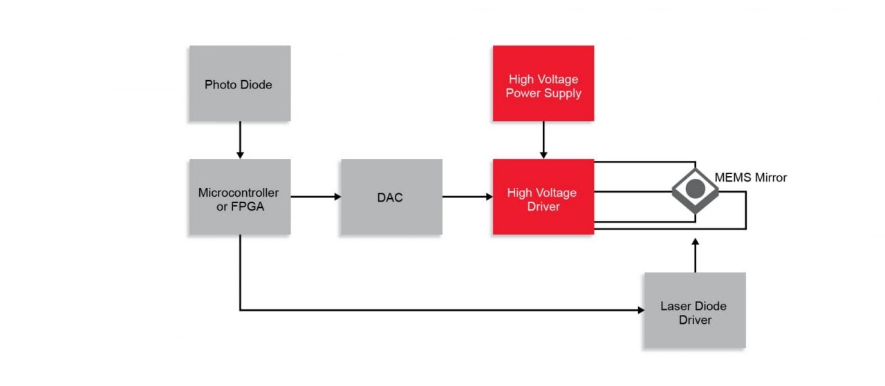
What Does a Typical MEMS Mirror System Look Like?
MEMS Mirror Steering Application Challenges
MEMS Laser Demo Available:
Introducing the Laser Demo-01, a development tool created by MEMS mirror supplier Mirrorcle Technologies, Inc. featuring control and drive electronics from Microchip Technology, Inc.
The development tool provides a means of evaluating laser beam steering technology, while enabling solutions development for many different consumer, industrial, automotive and other applications.
Featured Products
HV56264
The HV56264 is an AEC-Q100 rated quad high-voltage amplifier array integrated circuit. It operates on a 225V high-voltage supply and a 5.0V low-voltage supply.
- Four independent high-voltage amplifiers (225 VOUT swing)
- 11 V/µs typical slew rate (CLOAD = 15 pF)
- Adjustable gain by off-chip high-voltage resistors
- AEC-Q100 Grade 1 qualified
- Operating temperature (TJ) Range: −40°C to +125°C
HV265
The HV265 is a four-channel high-voltage operational amplifier gate array with an optional internal feedback resistor network.
- Four independent high-voltage amplifiers (205 VOUT swing)
- 0.02 V/µs minimum output slew rate for CLOAD to 200 pF (and ZOUT < 1 kOhm)
- Fixed gain of 82 V/V, 30 kHz gain-bandwidth product
- High-value internal feedback SiCr resistors to set gain (if internal gain set used)
HV264
The HV264 is a quad high-voltage amplifier array integrated circuit. It operates on a 225V high-voltage supply and a 5.0V low-voltage supply. It has optional internal gain set resistors.
- Four independent high-voltage amplifiers (215 VOUT swing)
- 9.0 V/µs typical output slew rate
- Fixed gain of 66.7 V/V
- Operating temperature (TJ) Range: −40°C to +125°C
HV9150
The HV9150 is a high-output voltages hysteretic mode step up DC/DC controller that has both a built-in charge pump converter and a linear regulator for a wide range of input voltage. The charge pump converter mode is ideal for battery-powered applications.
- Low input voltage: 2.7V
- Wide output voltage range: 6V to 500V
- 5W maximum output power with external MOSFET driver
- Built-in charge pump converter for the gate driver
MCP1633
The MCP1633 high-speed PWM controller is a pulse-width modulator developed for stand-alone power supply applications. It can be used as a boost converter for generating the high-voltage supply needed by High-Voltage (HV) drivers.
- Input voltage range: 3V to 5.5V
- Undervoltage lockout circuit
- Output overvoltage protection
- Output short circuit protection
- Overtemperature protection
- Small 16-pin QFN in 3 × 3 mm package
PIC32MZ Controller
- 32-bit MCU performance with up to 252 MHz/415 DMIPS
- Up to 2 MB Flash and 512 KB RAM
- 12-bit ADC @18 Msps, up to 48 channels
- Full-featured hardware crypto engine
- MPLAB® Harmony - a comprehensive, interoperable software development framework for PIC32 MCUs