Overview
This product has been EOL'ed (End of Life)
For new designs, we recommend using the following boards
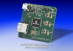
The dsPIC33E USB Starter Kit provides a low cost method for the development and testing of USB OTG, Host and Device applications on the 60 MIPS dsPIC33E DSC family. The board contains an on-board programming/debugger, standard A USB and micro A/B connectors, three user-programmable LEDs, three push button switches and an expansion header compatible with the I/O Expansion Board (DM320002). The starter kit comes preloaded with basic Communication Device Class (CDC) demonstration software.
Programming, Running and Debugging Applications
Use the following procedure for programming/debugging your application programs (the dsPIC33E Start Kit CDC USB Device Demo software available from the link below is mentioned here as an example):
- Using MPLAB IDE, open the project C:\dsPIC33E PIC24E USB Starter Kit Demo\Firmware\ USB Device - CDC - Basic Demo - dsPIC33E USB Starter Kit.mcp. (This assumes that the demo was installed in the default location)
- Connect the starter kit to your PC using the provided USB mini-B to full-sized A cable. Note that the jumper in J5 should not be installed.
- Choose “Starter Kit On Board” as the debugger tool in MPLAB IDE by selecting Debugger > Select Tool> Starter Kit On Board.
- Choose the debug build configuration by selecting Project > Build Configuration > Debug.
- Build the project by selecting Project > Build All.
- Download the code into the starter kit by selecting Debugger > Program.
- Run the downloaded application software by selecting Debugger > Run. At this time LED2 on the starter kit should turn on.
This demo allows the Starter Kit to appear as a serial (COM) port to the host. The instructions for this demo can be found at C:\dsPIC33E PIC24E USB Starter Kit Demo\Documentation\Getting Started\Getting Started - Running the Device - CDC - Basic Demo. See the Running the Demo section.
- On-board programming/debugger
- Standard A USB and micro A/B connectors
- Three user-programmable LEDs
- Three push button switches
- dsPIC33E USB Starter Kit Development Board with a dsPIC33EP512MU810-I/PT DSC
- dsPIC33E USB Starter Kit Information Sheet
- USB mini-B to standard cable - USB debug cable to debug and power the board
- USB micro-B to standard cable - USB cable to communicate with the dsPIC33E USB
Documentation
|
Title
|
Document Category
|
|||
|---|---|---|---|---|
| dsPIC33E Starter Kit CDC USB Device Demo | Code Examples | Download | ||
| dsPIC33E USB Starter Kit and PIC24E USB Starter Kit Users Guide | User Guide | Download | ||
| dsPIC33E USB Starter Kit and PIC24E USB Starter Kit Information Sheet | Miscellaneous | Download |