Loading
Log in to myMicrochip to access tools and benefits. Sign up in just one minute.
Maximize Your Experience: Reap the Personalized Advantages by Completing Your Profile to Its Fullest. Update Here
Stay in the loop with the latest from Microchip. Update your profile while you are at it. Update Here
Complete your profile to access more resources. Update Here
What Is Pulse-Width Modulation?
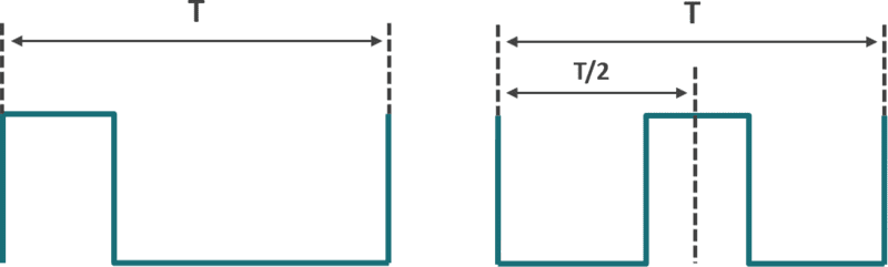
- The widely used edge-aligned PWM offers simple configuration, fast response and higher resolution
- The center-aligned PWM is extremely helpful in reducing the harmonics in the output of motor control, power supply and other applications
- Some select devices can even generate variable-aligned PWM, which serves applications that require higher flexibility
Although they are designed slightly differently for each architecture, the PWM peripherals available in PIC® and AVR® microcontrollers (MCUs) provide your system with a hardware-driven PWM generator that does not occupy any CPU resources at runtime. They also have built-in hardware to accommodate PWM-related tasks such as dead-band delay and auto shutdown. To generate complex waveform outputs, the PWM peripheral can be used with other on-chip peripherals, such as the Complementary Waveform Generator (CWG), Configurable Custom Logic (CCL) or Configurable Logic Cell (CLC). PWM peripherals can be easily configured with MPLAB® Code Configurator (MCC) for PIC MCUs and Atmel START for AVR MCUs.
PWM Peripherals in PIC MCUs
PIC MCUs offer a variety of stand-alone PWM peripherals ranging from 10–16 bits that are designed to integrate and interface with different peripherals like timers. The standard PWM peripheral generates a PWM signal with a modifiable period and duty cycle duty. A variety of clock sources can be used to operate the PWM, and it can be used in low-power sleep modes when an external clock source is being used.
Capture/Compare PWM Module in PIC MCUs
The Capture/Compare PWM (CCP) module is an extremely versatile peripheral that offers multiple modes of operation. In PWM mode, it can operate as a PWM peripheral, and in capture mode it can measure PWM characteristics such as the edges of waveforms. In compare mode, it can also compare its internal timer values to user-defined values to trigger other peripherals or generate an interrupt.
16-bit PWM with Dual Output in PIC MCUs
Select 8-bit PIC MCUs offer a 16-bit PWM that uses an independent Timer source and can generate various output signals. This PWM peripheral is extremely useful for dynamic high-resolution lighting control and push-pull amplifiers.

The PWM module has a compare feature and multiple outputs. The outputs are grouped in slices with each slice having two outputs where both share the same PWM period and operating mode. Different slices can utilize different operating modes. There are six operating modes: Left Aligned, Right Aligned, Center Aligned, Variable Aligned, Pulsed Compare, Toggled Compare. The left and right aligned modes can also be operated in Push-Pull mode.
Integrated PWM Outputs in AVR Timer/Counters
The PWMs in AVR MCUs are integrated in the Timer/Counter peripherals as a function or mode. Visit the Timer Peripheral page to learn about the functions of each Timer/Counter peripheral in AVR MCUs.
Almost all Timer/Counter peripherals in AVR MCUs provide the function of generating edge-aligned PWMs. This can be referred to as fast PWM or single-slope PWM mode within the Timer/Counter peripheral. Some Timer peripherals, like Timer/Counter Type A (TCA), have a split mode, which can be used to split a 16-bit PWM into two 8-bit PWMs in case your design needs more PWM outputs.
Some Timer/Counter peripherals, like Timer/Counter Type A or Timer/Counter0, 1, 2… on ATmega devices, can generate center-aligned PWMs. This can be referred to as phase correct PWM or dual-slope PWM mode within the Timer/Counter peripheral.
Looking for a MOSFET Driver?
We offer a wide array of MOSFET drivers for high-speed switching in low-side and high-side applications.

8-bit Microcontrollers with Pulse Width Modulation
Similar Devices
Tutorials and Examples
- Get Atmel START examples using the PWM
- Get MPLAB® Xpress examples using the PWM
- Get tutorials on Timers
Getting Started with AVR (10) Updating PWM Duty Cycle Using a Millisecond Timer
In this video, we will learn:
- Setting up a millisecond timer to update the duty cycle
- Using the 8-bit timer-counter 0 as a millisecond timer.
- Incrementing the duty cycle every 2 mS, resetting the duty cycle to 0 when it equals the period.
Follow along with the entire ‘Getting Started with AVR’ series.