We detect you are using an unsupported browser. For the best experience, please visit the site using Chrome, Firefox, Safari, or Edge. X
Maximize Your Experience: Reap the Personalized Advantages by Completing Your Profile to Its Fullest! Update Here
Stay in the loop with the latest from Microchip! Update your profile while you are at it. Update Here
Complete your profile to access more resources.Update Here!

The APM powers up and down analog peripherals on the microcontroller (MCU) in power-sensitive applications that do not require continuous analog operation. If a battery-operated sensor node only measures a voltage once per second, then power is wasted any remaining time the Analog-to-Digital Converter (ADC) is on.

How Does the APM Work?


In the initial state, with the peripherals turned off and the APM configured, the APM will start counting input clock pulses. When the number of clock pulses equals the set time for Start Event 1, which is the primary event, the APM will power up the peripherals that were selected in Start Event 1. The timer will now switch to counting an offset number of pulses. When (or if) Start Event 2 matches the count offset pulses, the peripherals selected for Start Event 2 will power up. The End Events behave similar to the Start Events; however, End Event 2, not End Event 1, will reset the APM back to the primary counting state. 

Example Use Case of the APM


The diagram on the right is a simple example that shows how you can use the APM to save power when sampling signals. Initially, the Analog-to-Digital Converter (ADC), Operational Amplifier (OPAMP) and Fixed Voltage Reference (FVR) are shut down. After a set length of time, the APM triggers the start of Event 1 to power up the OPAMP, ADC and FVR to prepare for analog signal measurement.

Next, the MCU waits for the peripherals to stabilize and the acquisition time to be met. Then, Event 2 powers up the digital converter in the ADC. After sufficient time has elapsed to complete the conversion, End Events 1 and 2 are set up to shut down all of the peripherals to save power and repeat the cycle. 
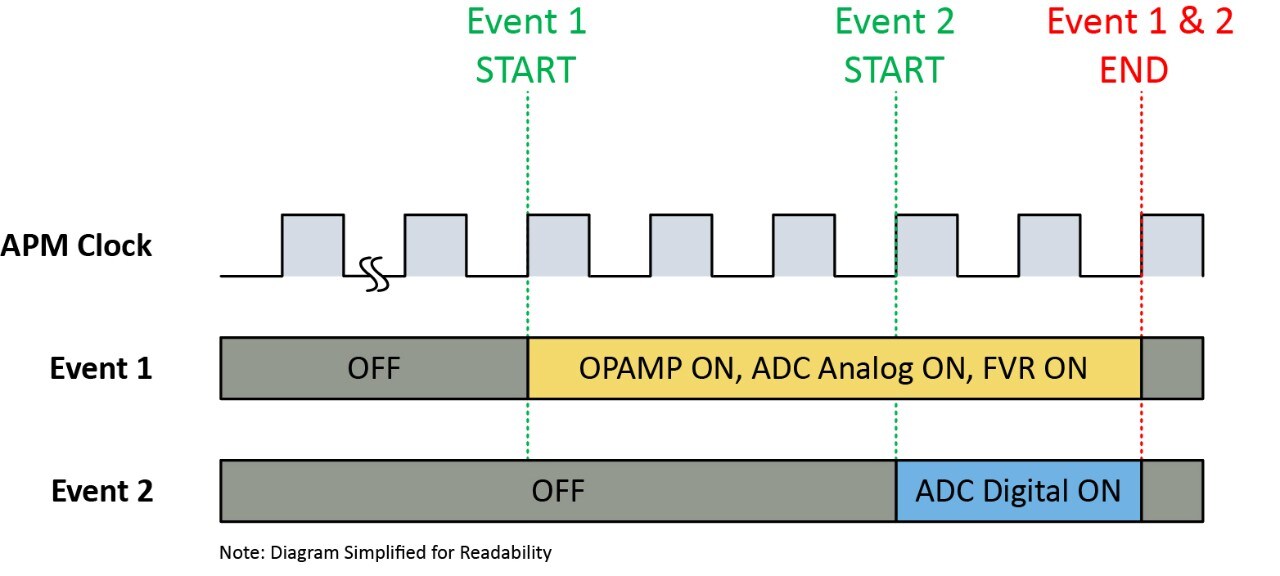
APM Example Use Case

Peripheral Integration


  • Analog-to-Digital Converter (ADC) with separate analog/digital power control
  • Digital-to-Analog Converter (DAC)
  • Fixed Voltage Reference (FVR)
  • Operational Amplifier (OPAMP/OPA)
  • Comparator (CMP)
  • Zero-Cross Detect (ZCD)

Note: This is not a full list of peripheral integrations and some may vary by device. Please consult the data sheet for more information.

Documentation


Title
TB3333-Basic Configurations of the Analog Peripheral Manager (APM) Download
Building a Low-Power Sensor Application Using APM Download