Overview
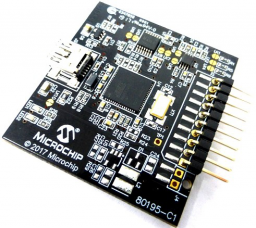
This maXTouch USB Bridge product provides an interface to convert I2C and debug signals to USB and communicate with the PC-based applications. This product is designed to be used with Microchip Automotive maXTouch touchscreen controllers.
Please contact your local Microchip representative for the latest bridge board firmware.
The ATUSB-I2C-AUTO-PCB automatically adapts the voltage levels for SDA, SCL, /CHG, /RESET, DBG_CLK and DBG_DATA signals depending on the connected maXTouch device. The valid VDD levels for these signals are between 1.6 V and 3.6 V.
While ATUSB-I2C-AUTO-PCB is a great choice for development, for touch sensor mass production consider the THW1027 "D21 maXTouch USB Bridge PCB" from 3rd party Promate. The THW1027 bridge board significantly improves data throughput, increasing test and production efficiency. The THW1027 bridge is twice as fast as the ATUSB-I2C-AUTO-PCB.
The communication interface between the bridge IC and the target may be either via the level shifter ICs or bypassing them:
Using Level shifter:
• VDD_BRIDGE must be 5V
• R6 + R7 are placed
• R8 + R13 are DNF
• LK3, LK5, LK6, LK7, LK8, LK9 are OPEN
Bypassing Level shifter:
• VDD_BRIDGE must be 3V3
• R6 + R7 are DNF
• R8 + R13 are placed
• LK3, LK5, LK6, LK7, LK8, LK9 are CLOSED
In either case, power for the VDD rail must be supplied from the host. The ATUSB-I2C-AUTO-PCB is not designed to supply power to a host system.
USB Bridge PCB
All released Windows versions.