Log in to myMicrochip to access tools and benefits. Sign up in just one minute.
Maximize Your Experience: Reap the Personalized Advantages by Completing Your Profile to Its Fullest. Update Here
Stay in the loop with the latest from Microchip. Update your profile while you are at it. Update Here
Complete your profile to access more resources. Update Here
Overview
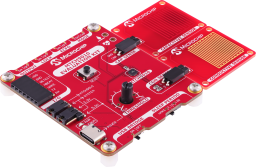
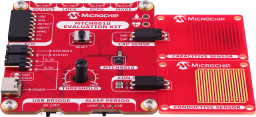
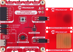
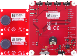
The MTCH9010 Evaluation Kit is a complete system designed to help users quickly familiarize themselves with the MTCH9010's capabilities. It includes two sensor boards: one capacitive and one conductive. The evaluation kit uses the MCP2221A USB to UART bridge for communication, allowing sensor data streaming and device configuration through the MTCH9010’s Enhanced Configuration Mode. The evaluation kit is designed to allow users to easily interface and test their own custom sensors with the MTCH9010, providing a versatile platform for rapid development and experimentation.
Liquid Detection and Indication
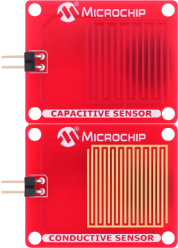
- Includes two sensor boards: one capacitive and one conductive
- Detect LED indicates liquid detection
- Heartbeat LED provides system status updates
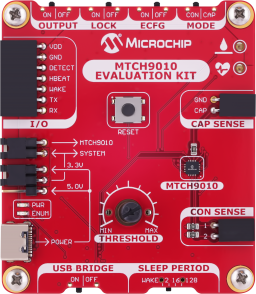
Configure the MTCH9010 using Slide Switches or UART
- Easy Configuration Using the Slide Switches:
- Select between capacitive or conductive sensing modes
- Adjustable liquid detection threshold via an on-board potentiometer
- Selectable sleep periods (four options) to optimize power consumption
- Enable sensor data streaming via UART
- Enable Enhanced configuration mode
- Advanced Configuration Using UART Interface:
- Access enhanced settings for more precise control and customization
USB to UART Communication
- MCP2221A USB to UART bridge for easy data logging and communication
- On-board status LED indicating successful enumeration with host computer
Multiple Power Options
- Directly power the board via USB for easy use
- On-board LDO ensures stable 3.3V operation for low-power applications
- Allows integration with external power sources for system evaluation
Reliable On-Board Power Management


Cannot load image!
Documentation
Filter by Document Type
Search Documentation
|
Title
|
Document Category
|
|||
|---|---|---|---|---|
| MTCH9010 Evaluation Kit User Guide | User Guides | PDF | HTML | ||
| AN5949 - Getting Started with the MTCH9010 Evaluation Kit | Application Notes | Link | PDF | HTML | |
| MTCH9010 Evaluation Kit Schematics | Board Design Files | Download | ||
| MTCH9010 Evaluation Kit Altium Project | Board Design Files | Download | ||
| MTCH9010 Evaluation Kit Design Documentation | Board Design Files | Download |