Log in to myMicrochip to access tools and benefits. Sign up in just one minute.
Maximize Your Experience: Reap the Personalized Advantages by Completing Your Profile to Its Fullest. Update Here
Stay in the loop with the latest from Microchip. Update your profile while you are at it. Update Here
Complete your profile to access more resources. Update Here
Overview
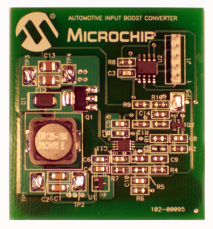
The MCP1630 Coupled Inductor Boost Converter Demo Board demonstrates Microchip's High-Speed Pulse Width Modulator (PWM) used in a coupled inductor design. When used in conjunction with a microcontroller, the MCP1630 device will control the power system duty cycle to provide different regulated output voltages from 15V to 40V using push button S1. The PIC12F683 microcontroller is used to generate oscillator pulses, reference voltage, output voltage selection and ON/OFF of Converter using push button S1.The MCP1630 device generates duty cycle based on various external inputs. External signals include the input oscillator pulses, reference voltage from PIC12F683 device, and the feedback voltage.
The PIC12F683 microcontroller is programmable, allowing the user to modify or develop their own firmware routines to further evaluate the MCP1630 device in this application.
The PIC12F683 microcontroller is programmable, allowing the user to modify or develop their own firmware routines to further evaluate the MCP1630 device in this application.
- With reduced stress on the MOSFET switch, provides greater degree of freedom in selecting the MOSFET
- Provides a varied output voltage selection from 15V to 40V in steps of 5V
- Push button select option for the required output voltage selection and ON/OFF control
The MCP1630 Coupled Inductor Boost Converter Demo Board demonstrates Microchip's High-Speed Pulse Width Modulator (PWM) used in a coupled inductor design. When used in conjunction with a microcontroller, the MCP1630 device will control the power system duty cycle to provide different regulated output voltages from 15V to 40V using push button S1. The PIC12F683 microcontroller is used to generate oscillator pulses, reference voltage, output voltage selection and ON/OFF of Converter using push button S1.The MCP1630 device generates duty cycle based on various external inputs. External signals include the input oscillator pulses, reference voltage from PIC12F683 device, and the feedback voltage.
The PIC12F683 microcontroller is programmable, allowing the user to modify or develop their own firmware routines to further evaluate the MCP1630 device in this application.
The PIC12F683 microcontroller is programmable, allowing the user to modify or develop their own firmware routines to further evaluate the MCP1630 device in this application.
Cannot load image!
Documentation
Filter by Document Type
Search Documentation
|
Title
|
Document Category
|
|||
|---|---|---|---|---|
| MCP1630/MCP1630V Data Sheet | Data Sheets | Download | ||
| PIC12F683 Data Sheet | Data Sheets | Download | ||
| MCP1630 Coupled Inductor Boost Demo Board Gerbers | Board Design Files | Download | ||
| MCP1630 Coupled Inductor Boost Demo Board Firmware | Software Libraries and Firmware | Download | ||
| MCP1630 Coupled Inductor Boost Converter Demo Board User's Guide | User Guide | Download |