Overview
ADM00855 are intended to provide a platform allowing customers to easily evaluate the features of the new MIC33M356 3A Power Modules in a buck converter application with output voltage and other settings either set via an I2C serial bus via a GUI interface. These boards are ideal for powering core supply voltages and also high power single-cell Li-ion battery powered applications. The evaluation boards also provide a reference for proper choice and PCB layout of components that are critical to switching regulator implementations.
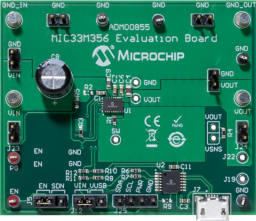
ADM00855 boards were developed to help engineers reduce product design cycle time and have an optimum platform to evaluate the performance of these devices. ADM00855 boards provide an onboard micro-USB port and the MCP2221 USB/I2C bridge to interface with the I2C Monitor GUI to configure and monitor the device registers.
The ADM00855 has the following features:
• Input Voltage Range 2.4V to 5.5V
• 3A (maximum) Continuous Output Current
• Multiple Faults Indication through I2C
• I2C Programmable:
- Output voltage: 0.6-1.28V, 5 mV resolution
- Slew rate: 0.2-3.2 ms/V
- Switching frequency: up to 2.5 MHz
- High-Side current limit: 3.5-10A
- Enable delay: 0.25 -3 ms
- Output discharge when disabled
• High Efficiency (up to 95%)
• ±1.5% Output Voltage Accuracy Overline/load/temperature Range
• Safe Start-Up with Pre-Biased Output
• Typical 1.5 μA Shutdown Supply Current
• Low Dropout (100% Duty Cycle) Operation
• Ultra-Fast Transient Response
• Latch-Off Thermal Shutdown Protection
• Latch-Off Current Limit Protection
• Power Good, Open-Drain Output
1x MIC33M356 3A Step Down Module Eval Board