Log in to myMicrochip to access tools and benefits. Sign up in just one minute.
Maximize Your Experience: Reap the Personalized Advantages by Completing Your Profile to Its Fullest. Update Here
Stay in the loop with the latest from Microchip. Update your profile while you are at it. Update Here
Complete your profile to access more resources. Update Here
Overview
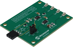
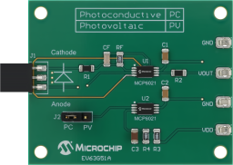
The Photodiode Light Detector Demo Board showcases how to use a transimpedance amplifier U1 (MCP6021) and external resistors, to convert photocurrent (IP) from a photodiode to an output voltage.
This board has two different circuit implementations, photovoltaic and photoconductive mode.
In the photoconductive topology, the photodetector needs to be reverse biased. Amplifier U2 provides a reverse bias of VDD/2 to the photodetector, where the photodetector's anode is the circuit GND.
In the photovoltaic topology, Amplifier U2 generates a reference voltage of VDD/2 so, that the circuit provides an output that is referenced to VDD/2 and allows an Analog-to-Digital Converter (ADC) to sample the signal with reference to the circuit GND.
- Supports Microchip MCP6021 and MCP6491 high precision operational amplifiers.
- Utilizes a transimpedance amplifier for sensor conditioning.
- On-board transimpedance amplifier (MCP6021)
- Inverting input configuration.
- Supports two different circuit implementations:
- Photovoltaic Mode
- Photoconductive Mode
- Test points available for connecting lab equipment.
- On-Board photodiode connector with two or three pin configurations.


Cannot load image!
Documentation
Filter by Document Type
Search Documentation
|
Title
|
Document Category
|
|||
|---|---|---|---|---|
| EV63G51A - Gerbers | Gerbers | Download | ||
| EV63G51A - Schematic | Schematics | Download | ||
| Photodiode Light Detector Solutions Demo Board User Guide | User Guides | Download | ||
| Using MCP6491 Op Amps for Photodetection Applications | Application Notes | Link | Download | |
| Amplifying High-Impedence Sensors ? Photodiode Example | Application Notes | Link | Download |