300W 1/16th Brick Power Module Reference Design
300W 1/16th Brick Power Module Reference Design | Reference Design
Third Party: EPC
Design Benefits:
- Industry-standard footprint and pinout
- High efficiency: 95.8% @ 12V/25A output
- Re-programmable output voltage and protection thresholds
Output voltage trimming
- Fault protection features
Key Features
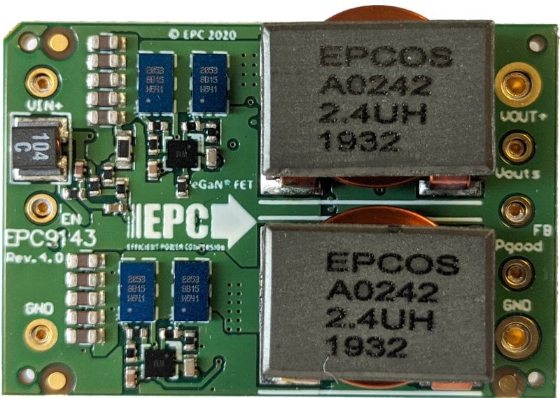
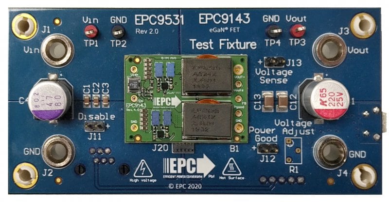
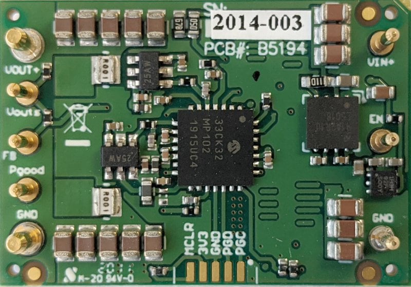
Brick DC-DC converters are widely used in data center, telecommunication and automotive applications, converting a nominal 48 V to different output nominal voltages such as 5 V, 9 V or 12 V. The standard dimension of the 1/16th brick converter is 33 x 22.9 mm (1.3 x 0.9 inch). The EPC9143 1/16th brick power module reference design, developed in collaboration with Efficient Power Conversion Corp. EPC, is designed for 48 V to 12 V DC/DC applications. It features the EPC2053 enhancement mode (eGaN®) field effect transistors (FETs), as well as a Microchip dsPIC33CK32MP102 16-bit digital signal controller (DSC). The height limit for this design is set to 10 mm (0.4 inch)
In DC/DC brick power module application, there is a continuous push towards higher power density given a fixed form factor. This reference design supports up to 300 W max. output power with 25 A output current at output voltages of 12 V, peak efficiency of >95%, and maximum power density of 730 W/in3 and demonstrates how dsPIC33C® DSCs are used to fully exploit the high performance of GaN FETs in fast switching Intermediate Bus Converter (IBC) applications.
The reference design firmware includes two modes of operation:
- Conventional Average Current Mode Control (ACMC): Multiloop controller with one outer voltage loop providing the same current reference IREF to two independent inner current loops for each phase, supporting control bandwidths of 2 kHz
- Advanced Type IV Voltage Loop Control (AVMC) with Enforced Cycle-By-Cycle PWM Steering, Gain Modulation and Current Balancing: A single, high-speed type IV voltage mode controller with enforced PWM steering is used to automatically create balanced phase currents in both phases of this interleaved converter. An underlying current balancing scheme compensates component tolerances and deviations over temperature. A built-in adaptive gain control algorithm stabilizes gain variations of the voltage loop controller during input- and output voltage transients, stabilizing cross-over frequency and output impedance, supporting control bandwidths of 25 kHz, for improved transient response, helping to minimize power distribution network (PDN) decoupling capacity
Key Features:
- Input Voltage: 18 … 61 V DC
- Output Voltage: 12 V DC
- Output Current: 25 A (max.)
- Operating Temperature: -40 … 110° C (Measured on FET package, airflow 800 LFM)
- High efficiency: 95.8% @ 12V/25A output
- Dimension: 33mm x 22.9 mm x 9 mm (1.30 in. x 0.90 in. x 0.35 in.)
- Industry-standard footprint and pinout
- Positive logic Enable
- Power Good output
- Constant switching frequency: 500 kHz
- Remote Sense
- Re-programmable output voltage and protection thresholds
Output voltage trimming
- Fault protection:
- Input under-voltage lock-out (UVLO)
- Input over-voltage lock-out (OVLO)
- Output over-current limit (OCL) (ACMC only)
- Output over-current protection (OCP) (AVMC only)
- Regulation error (REGERR)
For more information on hardware related documentation, design files and purchasing information, fill out the request form above.


