Overview
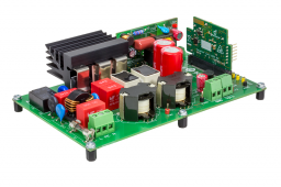
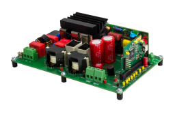
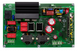
Low Voltage Power Factor Correction (LVPFC) Development Kit offers safe voltage levels at moderate power while designing algorithms on a boost power factor correction topology. These algorithms can be applied on real systems under development with minimal changes. The LVPFC Development Board utilizes the dsPIC33EP128GS806 device, supporting full digital and advanced power control algorithm schemes.
LVPFC development kit utilizes Isolation transformer with turn ratio of 10:1 and a 50W Active load. These additional tools are available from our third party tools provider ASCALAB .
Active Load can be bought directly from microchip Direct. For isolation transformer you can get in touch with your regional Microchip's sales executive.
The LVPFC Development Board is based on conventional Interleaved Boost Power Factor Correction (PFC) topology. The hardware supports 24 VAC input but the PCB has been designed following high-voltage design rules. With some modifications, the board can support universal offline voltage range 80 VAC to 260 VAC up to 200W output power
The main blocks of the LVPFC Development Board are:
- EMI/EMC Filter at the input (capable of high voltage)
- Bridge Rectifier (3Amax, capable of high voltage)
- Phase 1 (MOSFET, Current Transformer, Diode rectifier)
- Phase 2 (MOSFET, Current Transformer, Diode rectifier)
- Ultra-Wide Voltage Range (UWVR) 5W Flyback (capable of low and high voltage); It is providing 12V primary, non-galvanic isolated and 12V secondary, 4 kV galvanic isolated voltage
The LVPFC Development Board supports:
- Single-Phase or Dual-Phase Operation mode
- Discontinuous, Transition, Continuous Current mode of operation
- Input AC Voltage, Output DC voltage: resistive voltage divider sense
- Current Sense in each power switch leg: current transformers
- Zero Cross Detection (ZCD): auxiliary winding placed at storage chokes
- Inrush Current Limiter: Negative Temperature Coefficient (NTC) resistor and relay
- Output Overvoltage Protection (OVP): analog comparator with hysteresis, disabling gate drivers. Power reset (unplug the power) is needed to reset that comparator
- Mating Socket for DP PIM Board
- Low Voltage PFC Development Board
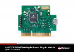
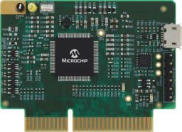
- Digital Power Plug-In Module (DP PIM)


Documentation
|
Title
|
Document Category
|
|||
|---|---|---|---|---|
| Low-Voltage Power Factor Correction Development Kit User's Guide | User Guide | Download | ||
| Boundary Mode Interleaved Low Voltage PFC Firmware | Software Libraries and Firmware | Download | ||
| dsPIC33EP128GS806 Digital Power PIM User's Guide | User Guide | Download | ||
| Microchip Power Board Visualizer Supporting dsPIC33 DSCs | Software Library Web | Link | ||
| Microchip PIC and AVR Tools | Software | Link |
| Tool Details |
|---|
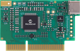
The dsPIC33AK512MPS506 Digital Power Plug-In Module (DP PIM) is a demonstration board that in conjunction with different power boards showcases the Microchip dsPIC3333CK512MPS506 Digital Signal Controller (DSC) features.
|
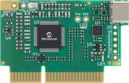
Evaluate this dsPIC33AK128MC106 Digital Power Plug-In Module (DP PIM) with the associated Digital Power Development Board and Low Voltage PFC Devlopment Kit.
|
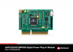
The dsPIC33CH512MP506 Digital Power Plug-In Module (DP PIM) is a demonstration board that showcases dsPIC33CH512MP506 16-bit Digital Signal Controller (DSC) features.
|
The dsPIC33CK256MP506 Digital Power Plug-In Module (DP PIM) is a demonstration board that showcases dsPIC33CK256MP506 16-bit Digital Signal Controller (DSC) features.
|
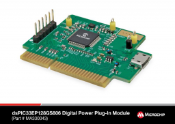
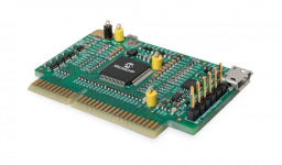
The dsPIC33EP128GS806 Digital Power Plug-In Module (DP PIM) is a demonstration board that showcases the Microchip dsPIC33EP128GS806 16-Bit Digital Signal Controller (DSC) features.
|
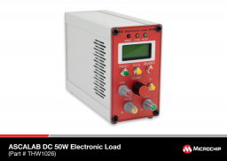
The ASC-50W compact electronic DC load, is the first generation of small desktop loads with a power rating of 50 Wmax. It offers voltage, current and power ratings for a multitude of applications for daily use in laboratories, schools or workshops.
|
This Plug-in Module (PIM) features a 100-pin dsPIC33CK512MPT608 Secure Digital Signal Controller (DSC) and can be used for evaluation of the dsPIC33CK512MPT608 and dsPIC33CK256MPT608.
|