Overview
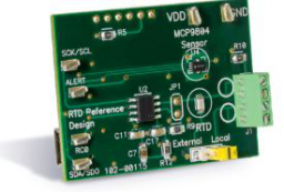
The RTD Reference Design demonstrates how to instrument Resistive Temperature Detector (RTD) and accurately measure temperature. This solution uses the MCP3551 22-Bit Analog to Digital Converter (ADC) to measure voltage across the RTD. The ADCand the RTD are referenced using an onboard reference voltage and the ADC inputs are directly connected to the RTD terminals. This provides a ratio metric temperature measurement. The solution uses a current limiting resistor to bias the RTD. It providesa reliable and accurate RTD instrumentation without the need for extensive circuitcompensation and calibration routines.
In addition, this reference design includes a silicon temperature sensor, MCP9804. This sensor is used for comparison only, it is not needed to instrument an RTD. The MCP3551 and MCP9804 outputs are read using a USB PIC® MCU. This controller is also connected to a PC using a USB interface. The Thermal Management software is used to plot the RTD temperature data in stripchart format.
Devices Supported: MCP3551, MCP9804
- Surface mount PT100 RTD
- External RTD connector (not included)
- Thermal Management GUI
- 22-Bit ADC MCP3551
- ±1°C Maximum accuracy temperature sensor MCP9804
- PIC18F2550 PIC® MCU
- USB interface to PC
The RTD Reference Design demonstrates how to instrument Resistive Temperature Detector (RTD) and accurately measure temperature. This solution uses the MCP3551 22-Bit Analog to Digital Converter (ADC) to measure voltage across the RTD. The ADCand the RTD are referenced using an onboard reference voltage and the ADC inputs are directly connected to the RTD terminals. This provides a ratio metric temperature measurement. The solution uses a current limiting resistor to bias the RTD. It providesa reliable and accurate RTD instrumentation without the need for extensive circuitcompensation and calibration routines.
In addition, this reference design includes a silicon temperature sensor, MCP9804. This sensor is used for comparison only, it is not needed to instrument an RTD. The MCP3551 and MCP9804 outputs are read using a USB PIC® MCU. This controller is also connected to a PC using a USB interface. The Thermal Management software is used to plot the RTD temperature data in stripchart format.
Devices Supported: MCP3551, MCP9804

Documentation
|
Title
|
Document Category
|
|||
|---|---|---|---|---|
| RTD Reference Design Board User's Guide | User Guide | Download | ||
| RTD Reference Design Board (TMPSNSRD-RTD2) Firmware | Software Libraries and Firmware | Download | ||
| Precision RTD Instrumentation for Temperature Sensing | Application Notes | Link | Download | |
| Thermal Management Utility (v1.6.2) | Software Libraries and Firmware | Download |