Overview
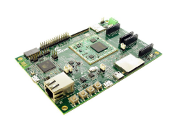
The ATSAMA5D27-SOM1-EK1 is a fast prototyping and evaluation platform for the SAMA5D2 based System in Packages (SiPs) and the SAMA5D27-SOM1 (SAMA5D27 System On Module). The kit comprises a baseboard with a soldered ATSAMA5D27-SOM1 module. The module features an ATSAMA5D27C-D1G-CU SIP embedding a 1-Gbit (128 MB) DDR2 DRAM. The SOM integrates a Power Management IC (PMIC), a QSPI memory, a 10/100 Mbps Ethernet PHY and a serial EEPROM with a MAC address. 128 GPIO pins are provided by the SOM for general use in the system. The board features a wide range of peripherals, as well as a user interface and expansion options, including two mikroBUS™ click interface headers to support MIKROE Click boards™ and one PMOD™ interface. Linux distribution and software package allows you to easily get started with your development.
Learn more how to add a WiFi connection to the ATSAMA5D27-SOM1-EK1.
Get started with AWS IoT here.
- ATSAMA5D27-SOM1 module:
- ATSAMA5D27C-D1G SiP - featuring a ATSAMA5D27C Cortex-A5 MPU running up to 500 MHz and embedding a 1Gb (128 MB) DDR2 DRAM
- MIC2800-G4JYML Power Management IC (PMIC) providing 3 power rails for the CPU, VDD I/O and the SDRAM
- SST26VF064B-104I/MF 64Mb Serial Quad I/O (QSPI) flash memory for boot code (Linux kernel or RTOS)
- KSZ8081RNAIA 10Base-T/100Base-TX Ethernet PHY for wired Ethernet connection
- 24AA02E48T-I/OT 2Kb Serial EEPROM with EUI-48 Note Identity for the Ethernet MAC address
- 1x CryptoAuthentication™ device ATECC508 (populated but not provisioned)
- USB: 1x USB host, 1x USB device, 1x USB HSIC (jumper not populated)
- 1x Ethernet interface RJ45 connector
- 1x CAN interface ATA6561
- LCD RGB 24-bit interface (50-pin FPC connector)
- Camera 12-bit interface (2x15 male connector)
- 1x Standard SD card interface, 1x microSD card interface
- 1x JLINK-OB and JLINK-CDC, x1 JTAG interface
- 1x RGB (Red, Green, Blue) LED
- 4x push button switches
- 1x tamper connector
- 1x PMOD connector
- 2x mikroBUS™ connector
- Power from USB A and USB JLINK-OB
- Power saving: SuperCap
Documentation
|
Title
|
Document Category
|
|||
|---|---|---|---|---|
| SAMA5D2 MPU SiP with up to 1Gbit DDR2 or 2Gbit LPDDR2 | Data Sheets | PDF | HTML | ||
| SAMA5D27-SOM1-EK1 Design and Manufacturing Files | Board Design Files | Download | ||
| SST26VF064B / SST26VF064BA 2.5V/3.0V 64 Mbit Serial Quad I/O (SQI) Flash Memory | Data Sheets | Download | ||
| 24AA02EXX/24AA025EXX/2K I2C Serial EEPROMs with EUI-48 or EUI-64 Node Identity | Data Sheets | Download | ||
| MIC2800 Digital Power Management IC 2MHz, 600mA DC/DC w/Dual 300mA/300mA | Data Sheets | Download | ||
| KSZ8081RNA/RND - 10Base-T/100Base-TX PHY with RMII Support | Data Sheets | Download | ||
| SAMA5D27 SOM1 Kit1 User's Guide | User Guide | PDF | HTML | ||
| System-On-Module (SOM) Assembly and Storage Guidelines | Application Notes | Link | PDF | HTML | |
| Developer Help ( Training Modules) | Software | Link |
| Tool Details |
|---|

The linux4sam website provides access to Microchip's Linux software and tool developments for our MPUs.
|
| Tool Details |
|---|
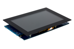
The High-Performance WVGA LCD Display Module with maXTouch Technology (AC320005-5) is designed for evaluating the Microchip's graphics display solution and graphics library for 32-bit microcontrollers and microprocessors. This 5-inch display is compatible with both versions of the Multimedia Expansion Board II (DM320005-2 or DM320005-5), as well as with Xplained Pro and Xplained Ultra evaluation kits. This board has a TFT 800 x 480 display with a 24-bit parallel RGB interface with a maXTouch technology capacitive touch interface.
|
| Tool Details |
|---|

The SAM-BA software tool supports in-system programming of Microchip ARM-based MCUs and MPUs.
|