Log in to myMicrochip to access tools and benefits. Sign up in just one minute.
Maximize Your Experience: Reap the Personalized Advantages by Completing Your Profile to Its Fullest. Update Here
Stay in the loop with the latest from Microchip. Update your profile while you are at it. Update Here
Complete your profile to access more resources. Update Here
Overview
This product is no longer available for sale.
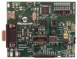
The MCP2120/22 Developer’s Board allows for the easy demonstration and development of IrDA applications. The board can be powered via USB or the power test points (VDD and GND). When using the power test points, if JP2 is shorted, the voltage must not exceed the PIC18F65J50 voltage specification.
The preprogrammed PIC18F65J50 firmware generates the MCP2122’s clock. The Host interface can be connected to the UART driver device (for IrDA to UART operation), for communication over the DB-9 connector or connected to the PIC18F65J50 for stand alone operation.
- Mini USB connector powers the board
- Onboard +3.3V regulator for powering PIC18F65J50
- Hooks for an external regulated DC supply
- Jumper to isolate PIC18F65J50 power signal from the rest of board power.
- DB-9 connector and associated hardware for direct connection to MCP2120 or MCP2122 UART
- UART signals routed by Four 3-pin jumpers to either DB-9 connector or the PIC18F65J50
- External Clock jumper
- Multiple Optical Transceiver circuits, one implemented
- Reset switch for PIC18F65J50 device
- ICSP Header for PIC18F65J50
- MCP2120 crystal socket
- MCP2120/22 SOIC and DIP Footprints (DIP package is the default installation)
The MCP2120/22 Developer’s Board allows for the easy demonstration and development of IrDA applications. The board can be powered via USB or the power test points (VDD and GND). When using the power test points, if JP2 is shorted, the voltage must not exceed the PIC18F65J50 voltage specification.
The preprogrammed PIC18F65J50 firmware generates the MCP2122’s clock. The Host interface can be connected to the UART driver device (for IrDA to UART operation), for communication over the DB-9 connector or connected to the PIC18F65J50 for stand alone operation.
The preprogrammed PIC18F65J50 firmware generates the MCP2122’s clock. The Host interface can be connected to the UART driver device (for IrDA to UART operation), for communication over the DB-9 connector or connected to the PIC18F65J50 for stand alone operation.
Other Requirements:
Requires a Second MCP212XDM board to operate any of the Demos described in the User's Guide
Requires a Second MCP212XDM board to operate any of the Demos described in the User's Guide
Cannot load image!
Documentation
Filter by Document Type
Search Documentation
|
Title
|
Document Category
|
|||
|---|---|---|---|---|
| MCP2120/22 Developer's Board User's Guide | User Guide | Download | ||
| MCP212XDM Gerbers | Board Design Files | Download | ||
| MCP212XDM Firmware | Software Libraries and Firmware | Download | ||
| Interfacing the MCP2122 to the Host Controller | Application Notes | Link | Download | |
| Using the MCP2120 Developer's Board of "IR Sniffing" | Application Notes | Link | Download | |
| Selecting an MCP21XX Device for IrDA® Applications | Application Notes | Link | Download | |
| Using the MCP2120 for Infrared Communications | Application Notes | Link | Download |