Overview
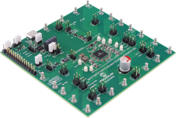
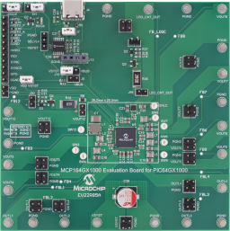
The MCP164GX1000 is a custom tailored Power Management Integrated Circuit (PMIC) specially developed as a high performance, small footprint, power companion for Microchip 64-bit RISC-V® Quad-Core Microprocessor PIC64GX1000. The MCP164GX1000 integrates 13 power channels distributed as eight parallelable 1.5A Buck regulators, four 300 mA LDOs, and one low-input/low-output voltage LDO Controller using an external MOSFET.
• Input Voltage: 2.7V to 5.5V
• Eight 1.5A Buck DC-DC Channels
• Four 300 mA High-Accuracy LDOs
• One High-Accuracy, High-PSRR LDO Controller Using External N-channel MOSFET(Q1)
• Output Voltage of 1V for Paralleled Bucks 1-2 and Current Capability of up to 3A (VDD Core Supply)
• Output Voltage of 3.3V for Buck 3 and Current Capability up to 1.5A (VDDIx GPIO Banks Supply)
• Output Voltage of 1.2V for Buck 5 and Current Capability of 1.5A (VDDIODDR (VDDI6) and Memory IO’s
Supply)
• Output Voltage of 1.8V for Buck 6 and Current Capability of 1.5A (VDD18 and VDDIx_1.8 Supply)
• Output Voltage of 2.5V for LDO 2 and Current Capability of 0.3A (VDD25, VDDA25, VDD_XCVR_CLK and DDR4
Core Supply)
• All other regulators available on the board are optional and turned off by default (Buck 4, Buck 7, Buck 8,
LDO 1, LDO 3, LDO 4 and the LDO Controller)
• 100% Duty Cycle Capability of Buck Channels
• Reference Ground (REFGND) is Routed to Bucks 1-2 for an Improved Accuracy of the Output Voltage
• Low-Noise Forced-PWM and Light-Load High-efficiency Mode Available (Pin-selectable or Bit Control)
• External Synchronization of Switching Frequency; this Feature can be Active or Disabled in Registry
• Selectable Phase (0°, 90°, 180° or 270°) for Buck Channels
• Global RESET (nRSTO_A) with Programmable De-Assertion Delay
• User-Defined RESET (nRSTO_P) with Programmable De-Assertion Delay
• 1 MHz MCP2221 I2C Interface; the PMIC has a Maximum of 3.4 MHz Frequency
• Dedicated VDD Supply Pin for NVM and Interface Allows Programming without Powering Up the Application
• Re-Configurable During Runtime
• Hiccup-Mode Current Limit for Buck Channels (can be Disabled)
• Programmable Thermal early warning and thermal shutdown protection
• LED Visual Indicator for the nINTO Pin (Interrupt Flag) with Selectable Interrupt Masking for Each Channel
• On-Board Load Transient Generator for VOUT12 and LDOC_OUT
• USB-C Connector for Easy Connection with Host PC
• General Purpose Output (GPO)


Documentation
|
Title
|
Document Category
|
|||
|---|---|---|---|---|
| I2C Monitor GUI | Software | Download | ||
| EV22R85A_BOM.pdf | Board Design Files | Download | ||
| EV22R85A_SCH.PDF | Board Design Files | Download | ||
| EV22R85A_GERBERS.zip | Board Design Files | Download | ||
| EV22R85A_Design_Files.zip | Board Design Files | Download | ||
| China-RoHS-Declaration_EV22R85A.pdf | Certifications | Download | ||
| UK-DoC_EV22R85A.pdf | Certifications | Download | ||
| EU-REACH-Statement_EV22R85A.pdf | Certifications | Download | ||
| EU-DoC_EV22R85A.pdf | Certifications | Download | ||
| MCP164GX1000 Evaluation Board User Guide | User Guides | Download |