Overview
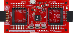
The PIC32MZ Mixed Signal Data Capture Board is a platform designed to facilitate communication between mixed-signal device demo boards (e.g., ADCs, DACs, DigiPots, Power Monitors) and their GUIs (Graphical User Interfaces). It supports communiction over SPI, I2C and UART through two mikroBUS™ sockets, as well as SQI™ via an additional 2x6 header, which are connected to separate peripherals within the microcontroller.
The UART and I2C lines of the second mikroBUS™ socket are also shared with a PicKit Serial 1x6 header for backward compatibility with boards designed for the PicKit Serial Analizer or the MCP2221A Breakout Module.
Power measurement on the mikroBUS™ power lines is made possible by a PAC1944 power monitoring IC and the power can be toggled ON or OFF via a button or software.
The microcontroller comes preprogrammed with a bootloader that communicates with a Bootloader Utility interface to download the appropriate firmware, depending on the connected demo board. Each supported demo board will use a specific set of communication protocols in the firmware tailored to its use case and the new firmware updates will come through the MCHP USB Bridge Service updates. If the board is repurposed for other applications using custom firmware, the EV64F02A_Bootloader.hex file is provided as a backup to restore the factory bootloader using an external PicKit or ICD programmer.
A generic SPI and I2C Data Capture GUI is also provided for scripted communication with any device connected to the mikroBUS™ sockets that communicates over these protocols, and the remaining I/O pins can also be toggled. The Bootloader Utility can be accessed from this GUI or directly using a web browser.
- Two mikroBUS™ sockets connected to separate microcontroller peripherals.
- Pickit Serial connector with UART and I2C signals shared with mikroBUS socket 2.
- Dedicated connector for SQI™ pins.
- Separate 150mA LDO for each 3.3V mikroBUS rail.
- Separate 300mA LDO for MCU.
- PAC1944 monitoring all four mikroBUS power rails (5V & 3.3V), communicating over a 3'rd I2C bus.
- mikroBUS™ Power Off button with MCU monitoring/override.
- MCU Reset button.
- BOOT button (or user configurable button).
- FW updates over USB using the factory bootloader and associated USB Bridge Service.
- EV64F02A PIC32MZ MXS Data Capture Board
- Micro USB cable.


Documentation
|
Title
|
Document Category
|
|||
|---|---|---|---|---|
| EV64F02A Mixed Signal Data Capture Evaluation Board User Guide | User Guides | Download | ||
| MCHP USB to TCP Bridge Service User's Guide | User Guide | Download | ||
| Data Capture GUI v1.0.2 | Software Tools | Download | ||
| MCHP USB Bridge Service v1.0.12 | Software Tools | Download | ||
| EV64F02A Schematic | Schematics | Download | ||
| EV64F02A 3D PDF | Other Board Design Files | Download | ||
| EV64F02A BOM | BOM | Download | ||
| EV64F02A Gerbers | Gerbers | Download | ||
| EV64F02A Design Files | Board Design Files | Download | ||
| EV64F02A Bootloader v3.6 | Sample Code | Download |