Integrated Level Shifters in PIC® Microcontrollers
Learn about the integrated level shifters, also known as Multi-Voltage I/O (MVIO) ports, inside the PIC18-Q24 family of microcontrollers.

Mastering Voltage Challenges in Embedded Design
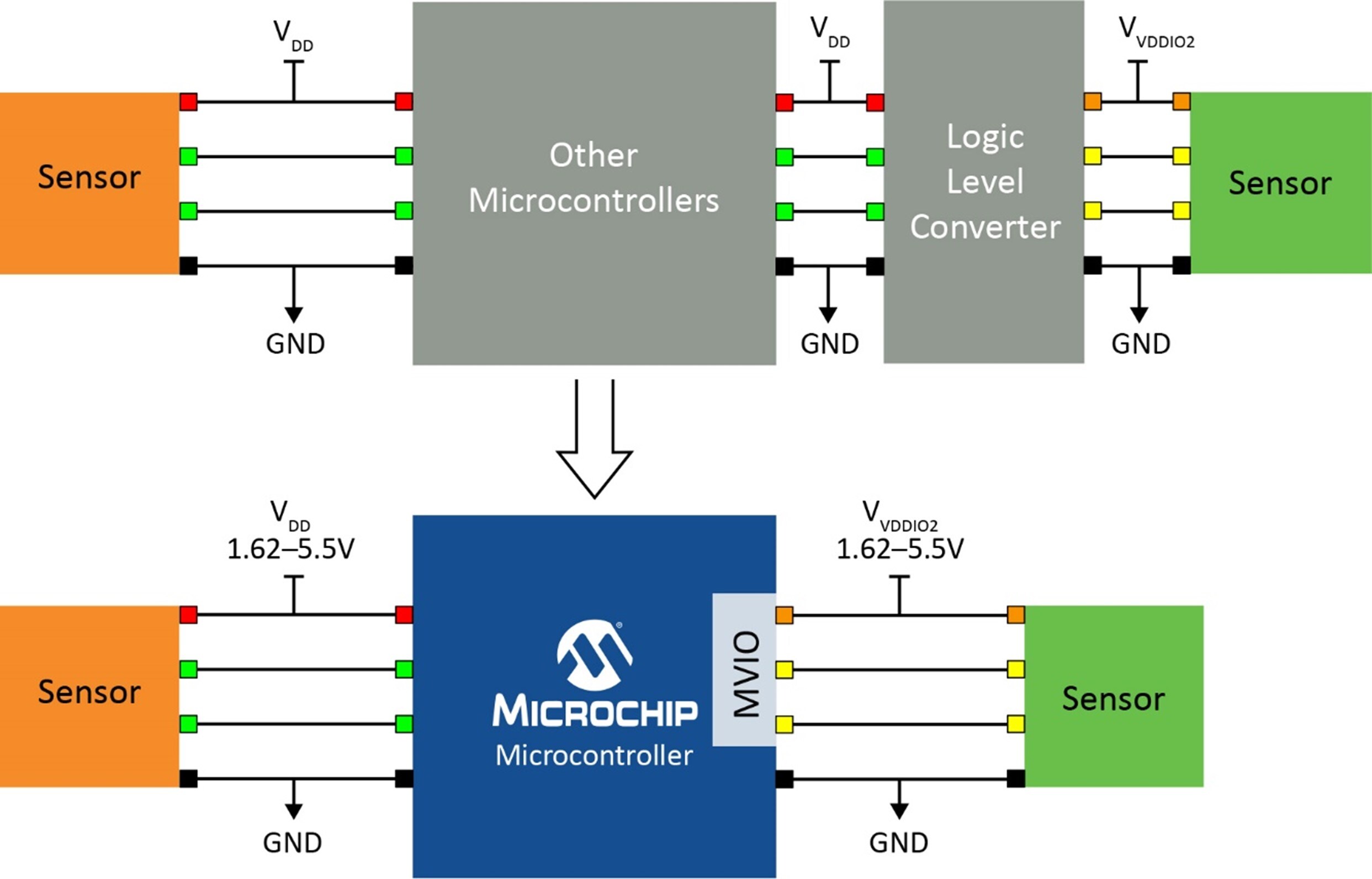
A common challenge in embedded design is mismatched voltage levels, where a sensor or peripheral operates in a different voltage domain than the microcontroller. If these devices were connected, two possibilities could occur:
- The lower voltage device would exceed its input ratings.
- The higher voltage device may not be able to differentiate a “1” from a “0” from the lower-voltage device side.
A common solution to this problem is to use a level-shifter, which converts from one voltage domain into another. While these are standard parts, it adds to the Bill of Materials (BOM) and requires extra PCB area. Additionally, the configuration and feature set of the level-shifter will vary depending on the direction of the signals and other characteristics.
Another solution is to use integrated level-shifting I/O ports known as Multi-Voltage I/O (MVIO) in PIC® and AVR® microcontrollers. MVIO ports are I/O ports that operate in a different voltage domain than the rest of the microcontroller. This is true bi-directional level-shifting, not just high voltage tolerant pins.

The MVIO voltage domain can be higher or lower than the core of the microcontroller, as long as the I/O port is above the minimum operating level and below the absolute maximum ratings of the device (in most cases this is 1.62V to 5.5V). While the MVIO I/O is powered separately, the I/O port operates like a normal digital I/O port to the microcontroller and its hardware peripherals. The pins can be assigned I/O directions, output values and/or other parameters (such as open drain, Weak Pull-Up, etc.). On PIC MCUs, MVIO works with Peripheral Pin Select (PPS), while on AVR PORTMUX can be used to route peripheral signals, as usual.
MVIO ports are powered independently of the main microcontroller. In other words, there is no power sequencing required. An MVIO port can be powered while the microcontroller is offline, or the port can be left unpowered while the microcontroller runs. In either case, no damage occurs to the microcontroller.
Outside of the standard digital I/O functions, MVIO also has extra hardware for applications to detect power events on the MVIO port and measure the current power supply voltage. The specific behavior will vary from device to device and across architectures (PIC or AVR), so this post will only discuss the MVIO features as implemented on the PIC18-Q24 family of MCUs. The Tech Brief, Using the Multi-Voltage I/O Module on 8-bit PIC and AVR Microcontrollers (TB3351), goes into more detail about how the MVIO is configured on both architectures.
The PIC18-Q24 family has two interrupts and an internal Analog-to-Digital Converter (ADC) channel for the MVIO voltage at runtime. The ADC measures the current MVIO supply voltage through an internal 10x divider to ensure the MVIO voltage is within the measurable range of the ADC, as it can be higher than the core voltage. The interrupts are from an internal voltage monitor dedicated to the MVIO module and can be switched off to save power.
The voltage monitor generates the interrupts VDDIOxLVDIF and nVDDIOxnRDYIF. These interrupts are level-sensitive, not edge-sensitive, meaning they stay asserted while the condition exists. The associated status flags can also be polled in software.
The nRDYIF interrupt is asserted when the MVIO port is below the required minimum operating voltage, at which the MVIO port is disabled. LVDIF interrupt is asserted if the MVIO port falls below a configurable threshold, which allows the developer to detect when the power supply is dropping, but before the power supply fully collapses.
By using these features with the MVIO peripheral, many of the challenges of interfacing between different voltage domains can be solved. MVIO is nearly transparent to the microcontroller, which simplifies development of these applications. For more information about how to implement MVIO, please read TB3351 and the device data sheet. Visit the device web page for more information about the PIC18-Q24 family of microcontrollers or our parametric table to see a pre-sorted table of all devices with MVIO.