Implementing Hysteresis in the ADCC
Learn how to use the setpoint register in enhanced ADC peripherals to implement hysteresis in results to filter out noise.
The Analog-to-Digital Converter with Computation (ADCC) [and Context (ADCCC)] are enhanced ADC peripherals that offload some aspects of signal processing from the Central Processing Unit (CPU). For instance, these peripherals can be configured to acquire a set number of samples, average them together, and produce an interrupt if a specific condition occurs with regards to the filtered (computed) result. These features both reduce the load on the CPU and can operate when the CPU is in sleep.
This example was written for the PIC18-Q43 family of microcontrollers, however with the appropriate modifications, it should be compatible with other microcontrollers containing the ADCC or ADCCC peripherals as well.
For more information about these peripherals, please see the Enhanced ADC page.
Implementation
One of the features of the enhanced ADCs is the ability to trigger an interrupt based on a threshold test. The implementation puts the hysteresis point in the setpoint register (ADSTPT) of the ADCC. When the result (ADRES) is acquired, an error value (ADERR) is calculated. ADERR has multiple modes of calculation, but the mode in use for this example is:
ADERR = ADRES – ADSTPT
ADERR contains the difference between the result and the setpoint. To trigger the threshold interrupt, the ADCC has been setup to use the following threshold test:
ADERR < ADLTH (Lower Threshold) OR ADERR > ADUTH (Upper Threshold)
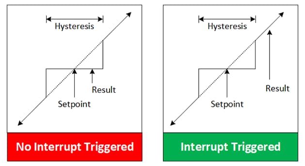
If the test condition is true, then the threshold interrupt is generated. At this point, the setpoint must be updated with the resulting value from ADRES to update the center point of the hysteresis. This can be done in the interrupt service routine or the interrupt signal can be used to start a Direct Memory Access (DMA) transfer from ADRES to ADSTPT. The example program provided uses an interrupt-based approach, whereas the Voltage-to-Frequency (V/F) converter uses a Direct Memory Access (DMA) driven approach to automate updates.
Use Cases
This application can be used in a few different ways. The first is a digital version of an analog comparator. Ordinarily, a Digital-to-Analog Converter (DAC) or other external source would set a reference level for the comparator. However, if no DAC outputs could be spared and an external source isn’t available, this configuration would provide similar functionality. The auto-update could be disabled to keep the comparator level constant.
Another option would be to filter out noise. If the ADC is acquiring samples, and there is noise present, the hysteresis could be used to provide some additional noise immunity. An example of this is shown in the Voltage-to-Frequency Converter, which oversamples and averages the ADCC for a higher-resolution result, but is extremely vulnerable to noise. The hysteresis helps to reduce frequency jitter caused by random noise.
Demo Example: https://github.com/microchip-pic-avr-examples/pic18f57q43-hysteresis-adcc-mplab-mcc