Log in to myMicrochip to access tools and benefits. Sign up in just one minute.
Maximize Your Experience: Reap the Personalized Advantages by Completing Your Profile to Its Fullest. Update Here
Stay in the loop with the latest from Microchip. Update your profile while you are at it. Update Here
Complete your profile to access more resources. Update Here
Overview
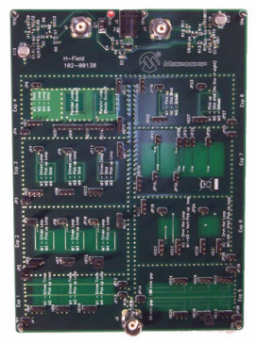
The Magnetic Field Evaluation Board (104-00138) is designed to demonstrate H-field coupling under various conditions. These experiments will help system designers understand the impact PCB layout techniques have on controlling magnetic coupling in their design.
The Magnetic Field Evaluation Board supports measurement of inductive (magnetic) trace-to-loop and loop-to-loop coupling, with and without shielding by planes.
Some experiments examine strong horizontal between layer loop-to-loop coupling, where shielding effects are easily demonstrated. Other experiments examine typical PCB trace configurations, where loop areas are much smaller and effects of distance are easily demonstrated.
Limited by Gain Bandwidth of the on-board common-base Gain=100 signal booster [needs 9V], experiments are run from 1 kHz to 10 MHz, to demonstrate how inductive coupling is dependent on frequency.
With 5V AC input [yielding 0.1 amp peak-to-peak into 50 ohm load], amplifier output amplitudes are .002V to 2 volts.
N/A
The Magnetic Field Evaluation Board (104-00138) is designed to demonstrate H-field coupling under various conditions. These experiments will help system designers understand the impact PCB layout techniques have on controlling magnetic coupling in their design.
The Magnetic Field Evaluation Board supports measurement of inductive (magnetic) trace-to-loop and loop-to-loop coupling, with and without shielding by planes.
Some experiments examine strong horizontal between layer loop-to-loop coupling, where shielding effects are easily demonstrated. Other experiments examine typical PCB trace configurations, where loop areas are much smaller and effects of distance are easily demonstrated.
Limited by Gain Bandwidth of the on-board common-base Gain=100 signal booster [needs 9V], experiments are run from 1 kHz to 10 MHz, to demonstrate how inductive coupling is dependent on frequency.
With 5V AC input [yielding 0.1 amp peak-to-peak into 50 ohm load], amplifier output amplitudes are .002V to 2 volts.
The Magnetic Field Evaluation Board supports measurement of inductive (magnetic) trace-to-loop and loop-to-loop coupling, with and without shielding by planes.
Some experiments examine strong horizontal between layer loop-to-loop coupling, where shielding effects are easily demonstrated. Other experiments examine typical PCB trace configurations, where loop areas are much smaller and effects of distance are easily demonstrated.
Limited by Gain Bandwidth of the on-board common-base Gain=100 signal booster [needs 9V], experiments are run from 1 kHz to 10 MHz, to demonstrate how inductive coupling is dependent on frequency.
With 5V AC input [yielding 0.1 amp peak-to-peak into 50 ohm load], amplifier output amplitudes are .002V to 2 volts.
Cannot load image!