Overview
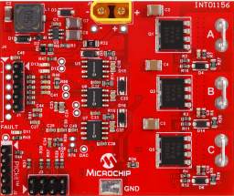
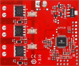
The E-Scooter Reference Design targets high-performance, cost-effective motor control applications, particularly lower-power E-mobility solutions: E-scooters, E-bikes or power tools. Powered by a dsPIC33CK64MP105 motor control digital signal controller (DSC), the E-Scooter Reference Design is able to drive BLDC/PMSM motors of up to 350W power and up to 20A RMS phase currents. The input voltage range is between 18 to 42 volts, covering applications powered from battery strings of up to 10s (Li-Ion cells). The board supports Hall sensored and sensorless (BEMF or FOC) motor control algorithms. The supplied firmware uses Hall sensors for high-torque start-up and low-speed operation and switches to FOC for better battery efficiency and to support higher speeds. It also includes regenerative braking. The board is developed to meet the stringent demands of modern motor control applications providing high efficiency, compact dimensions, low cost, and high performance.
For additional details and design files please visit the reference design page.
- dsPIC33CK64MP105 DSC 16-bit motor controller:
- Demonstration software using Hall sensors for high-torque start-up and FOC for high-efficiency; includes regenerative braking
- PICkit™ debugger/programmer interface for MPLAB PICKit4, ICD4, etc.
- Feedback circuits support both Hall sensors and sensorless motor control algorithms (BEMF and FOC)
- PWM switching frequency range from 8-50kHz (typical 20kHz - above the audible range)
- 3-Phase inverter stage:
- 3 MPC4104 half-bridge MOSFET gate drivers
- 6 N-Channel MOSFETs with low RDS(on) (typical 1.9 mΩ)
- 3 Low-side shunt resistors on each inverter phase for current measurement (2mΩ)
- 350W maximum output power
- 20A RMS (continuous) and up to 27A RMS (momentary) motor phase current
- Faston connectors to motor
- 18-42V Vbus input voltage range (up to 10s battery pack):
- XT30 type connector for battery pack
- System bias generation using the MCP16331 (12V), MCP1754S (5V), and MCP1754S (3.3V)
- Temperature measurement support (NTC thermistor)
- Auxiliary connector for other functions: throttle input, voltage monitoring, I2C, UART, Bluetooth, etc.