
Understanding the ASA-ML Protocol Stack: A System Level View
As automotive camera architectures grow more complex, connectivity requires more than a physical interface. This post breaks down the ASA-ML protocol stack, including TDD, data link, encapsulation, timing and security layers, and explains how they enable scalable, synchronized ADAS systems.
Introduction: Why the Protocol Stack Matters
When engineers talk about camera connectivity, the conversation often starts and ends with the physical layer. But as camera counts increase and vehicle architectures evolve, connectivity problems stop being PHY‑only problems.
The ASA‑ML specification takes a different approach. Instead of defining just a link, it defines a complete protocol stack, explicitly addressing the layers required to transport video data, control information, timing and security in automotive systems.
Understanding this stack is essential for system architects evaluating how ASA‑ML fits into modern ADAS and camera architectures.
A Full Connectivity Framework — Not Just a SerDes
ASA‑ML defines a multi‑layer architecture that includes:
- Physical layer
- Data link layer
- Encapsulation of application and control data
- Security entity
- Precision timing delivery
This stack ensures consistent behaviour across:
- Different camera types
- Different data rates
- Different vehicle topologies
Rather than treating each layer as an afterthought, ASA‑ML integrates them into a cohesive framework.
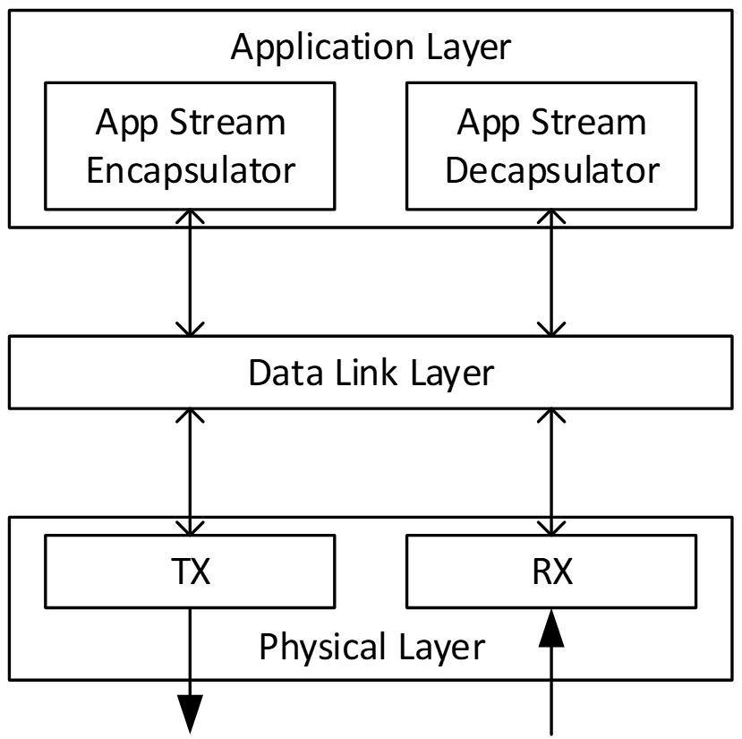 |
Figure 1 – ASA protocol stack
Physical Layer: Optimized for Automotive Reality
At the foundation of the stack is the physical layer, which uses time‑division duplexing (TDD) rather than frequency‑division duplexing.
Key characteristics:
- Upstream (US) and downstream (DS) traffic share the same cable, separated in time
- Bandwidth can be flexibly allocated by adjusting burst structure
- Shared baud rates simplify design across use cases
This choice reflects the highly asymmetric nature of camera systems, where downstream video traffic dominates, while upstream control traffic is comparatively light.
Data Link Layer: Reliable Transport for Sensor Data
Above the physical layer, the data link layer (DLL) is responsible for:
- Framing and transporting data reliably
- Supporting both application data and control information
- Leveraging physical‑layer error protection mechanisms
By handling these functions consistently across devices, the DLL contributes to multi‑vendor interoperability, one of ASA‑ML’s core goals.
Encapsulation: Carrying Video and Control Together
Camera systems are not just streaming raw video. They also require control messaging for:
- Sensor configuration
- Status monitoring
- Operational coordination
ASA‑ML includes defined mechanisms for encapsulating both application data streams and control data within the link.
From a system perspective, this avoids the need for parallel communication paths and simplifies integration at the ECU or zonal controller.
Security Entity: Designed Into the Stack
Security is treated as a first‑class element within the ASA‑ML stack, rather than an external add‑on.
While the blueprint does not position ASA‑ML as a cybersecurity standard, it clearly defines security as part of the connectivity framework. This ensures:
- Consistent treatment across vendors
- Predictable integration into system architectures
For architects, this reinforces the importance of evaluating connectivity standards at the system policy level, not just the signal level.
Precision Timing Delivery: Coordinated Sensing Matters
Multi‑camera ADAS systems depend on accurate timing alignment, particularly when sensor data is fused for perception or decision‑making.
ASA‑ML explicitly includes precision timing delivery as part of its stack.
This design choice acknowledges that camera links are part of a time‑sensitive system, where synchronization impacts downstream processing quality.
How the Stack Fits Real Architectures
The ASA‑ML protocol stack is designed to operate within:
- Star topologies, with point‑to‑point links between cameras and an ECU
- Zonal topologies, where local controllers aggregate multiple sensors
Because the same stack applies across these topologies, architects can evolve system layouts without rethinking the fundamentals of data transport.
Optional elements like the link aggregation sublayer further support scalability by allowing multiple physical links to be combined.
Why Architects Should Care
Looking at the stack holistically reveals why ASA‑ML differs from earlier approaches:
- Connectivity decisions affect power, thermal behavior and scaling
- PHY choices influence higher‑level design simplicity
- Standardized layers reduce long‑term integration risk
ASA‑ML’s protocol stack is a reflection of these system‑level realities, not a collection of independent features.
What’s Next in This Series
In the next article, we’ll take a closer look at why ASA‑ML uses time‑division duplexing (TDD) and how that single architectural choice influences:
- Bandwidth allocation
- Power‑over‑coax design
- PHY reuse and SKU strategy
Want More?
Download the ASA‑ML Blueprint Tutorial (DS50004072) for the full technical explanation of the protocol stack and its system implications.
Read part one of this series on the blog.